Mitsubishi Lancer Evolution IX. Manual - part 523
 

  Index      Mitsubishi     Mitsubishi Lancer Evolution IX - service repair manual


Search            


Content   ..  521  522  523  524   ..


Mitsubishi Lancer Evolution IX. Manual - part 523


TROUBLESHOOTING

ANTI-SKID BRAKING SYSTEM (ABS)

35B-123

INSPECTION PROCEDURE 4: The ABS Warning Lamp Remains Illuminated after the Engine is 
Started.

NOTE: This diagnosis procedure is limited to cases where communication with the M.U.T.-II/III is possible 
(ABS-ECU power supply is normal) and no diagnosis code is set.

ABS WARNING LAMP CIRCUIT

Refer to 

P.35B-118

.

CIRCUIT OPERATION

Refer to 

P.35B-118

.

COMMENT ON TROUBLE SYMPTOM

The cause is probably the ABS-ECU malfunction.

PROBABLE CAUSES

The most likely causes for this case are:

• Damaged wiring harness or connector

• Malfunction of the brake modulator hydraulic unit 

(integrated with ABS-ECU)

DIAGNOSIS

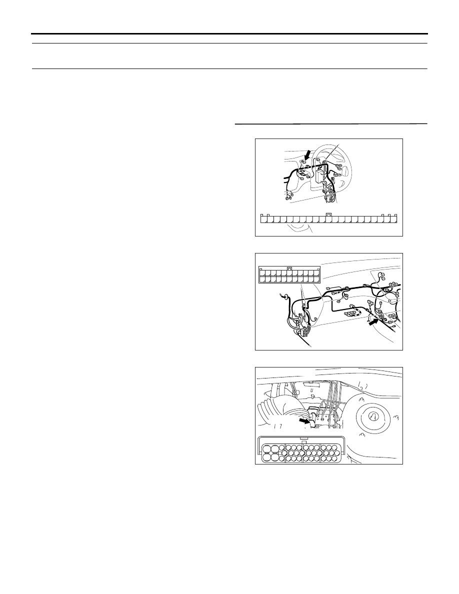
STEP 1. Check the following connectors.

Combination meter connector C-01

Intermediate connector C-122

ABS-ECU connector B-118
Check the connectors for loose, corroded or dam-
aged terminals, or terminals pushed back in the con-
nector.

Q: Are the connectors and terminals in good 

condition?
YES : 

Go to Step 2.

NO : 

Repair it and then go to Step 4.

AC311161

1

2

3

4

5

6

7

8

9

10

11

12

13

14

15

16

17

18

19

20

21

Connector C-01 (harness side)

AD

Connector: C-01

AC311160AC

Connector: C-122

C-122 (L)

2

1

3

13

12

14

21

10

5

4

6

16

15

17

7 8 9

19

18

20

11

22

AC311127AB

B-118 (B)

Connector: B-118

28

32

34

12

11

33

30

21

9

10

22

31

7

8

29

20 19

24

2

26

4

5

6

27

18 17

3

25

16 15

1

23

13

14

Harness side

TROUBLESHOOTING

ANTI-SKID BRAKING SYSTEM (ABS)

35B-124

STEP 2. Check the following harness wire.

The wire between combination meter connector C-01 
(terminal 13) and ABS-ECU connector B-118 (termi-
nal 27)

Q: Is the harness wire damaged?

YES : 

Repair or replace it and then go to Step 4.

NO : 

Go to Step 3.

STEP 3. Check the ABS warning lamp circuit at 
ABS-ECU connector B-118.

(1) Disconnect ABS-ECU connector B-118 and 

check at the harness side connector.

(2) Turn the ignition switch to the "ON" position.
(3) Earth terminal 27 and check the ABS warning 

lamp.

Q: Does the ABS warning lamp go off?

YES : 

Replace the brake modulator hydraulic unit 

(integrated with ABS-ECU) (Refer to 

P.35B-143

). Then go to Step 4.

NO : 

Replace the combination meter (Refer to 
GROUP 54A, Combination Meter Assembly 

P.54A-56

). Then go to Step 4.

STEP 4. Retest the system.

Q: Does the ABS warning lamp turn off in 3 seconds 

after start-up?
YES : 

The procedure is complete.

NO : 

Return to Step 1.

AC311161

1

2

3

4

5

6

7

8

9

10

11

12

13

14

15

16

17

18

19

20

21

Connector C-01 (harness side)

AD

Connector: C-01

AC311127AB

B-118 (B)

Connector: B-118

28

32

34

12

11

33

30

21

9

10

22

31

7

8

29

20 19

24

2

26

4

5

6

27

18 17

3

25

16 15

1

23

13

14

Harness side

AC311168

28

32

34

12

11

33

30

21

9

10

22

31

7

8

29

20 19

24

2

26

4

5

6

27

18 17

3

25

16 15

1

23

13

14

Connector B-118
(harness side)

AE

B-118 (B)

Connector: B-118

TROUBLESHOOTING

ANTI-SKID BRAKING SYSTEM (ABS)

35B-125

INSPECTION PROCEDURE 5: In the Inspection with the M.U.T.-II/III Data List, the Parking Brake 
Switch is not Turned ON or Turned OFF.

OPERATION

The ABS-ECU monitors the parking brake switch to 
optimise the ABS control.

COMMENT ON TROUBLE SYMPTOM

The cause may be an open or a short circuit between 
the parking brake switch and the ABS-ECU.

PROBABLE CAUSES

The most likely causes for this case are:

• Damaged wiring harness or connector

• Malfunction of the parking brake switch

• Malfunction of the brake modulator hydraulic unit 

(integrated with ABS-ECU)

ABS-ECU

PARKING
BRAKE
SWITCH

Wire colour code
B : Black     LG : Light green
G : Green     L : Blue
W : White     Y : Yellow
SB : Sky blue     BR : Brown
O : Orange     GR : Gray
R : Red     P : Pink     V : Violet

Parking Brake Switch Circuit

TROUBLESHOOTING

ANTI-SKID BRAKING SYSTEM (ABS)

35B-126

DIAGNOSIS

STEP 1. M.U.T.-II/III data list.

CAUTION

To prevent damage to M.U.T.-II/III, always turn the 
ignition switch to the "LOOK" (OFF) position 
before connecting or disconnecting M.U.T.-II/III.

(1) Connect M.U.T.-II/III as shown in the illustration.
(2) Start the engine.

(3) Set M.U.T.-II/III to data reading mode for following 

item.

• Item No.29: Parking brake switch

OK: 

Q: Is the parking brake switch input normal?

YES : 

This malfunction is intermittent. Refer to 

GROUP 00, How to Use 
Troubleshooting/Inspection Service Points 

− 

How to Cope With Intermittent Malfunction 

P.00-5

NO : 

Go to Step 2.

STEP 2. Check the parking brake switch circuit. 
Resistance measurement at ABS-ECU connector 
B-118.

(1) Disconnect ABS-ECU connector B-118 and 

measure at the harness side.

AC311157

Steering shaft

AB

MB991502

<Using the M.U.T.-II>

AC311153

AB

MB991911

16-PIN

MB991827

MB991824 

<Using the M.U.T.-III>

Checking requirement

Display

Pull the parking brake lever

ON

Release the parking brake lever

OFF

AC311168

28

32

34

12

11

33

30

21

9

10

22

31

7

8

29

20 19

24

2

26

4

5

6

27

18 17

3

25

16 15

1

23

13

14

Connector B-118
(harness side)

AF

B-118 (B)

Connector: B-118


Content   ..  521  522  523  524   ..