Mitsubishi Lancer Evolution IX. Manual - part 495
 

  Index      Mitsubishi     Mitsubishi Lancer Evolution IX - service repair manual


Search            


Content   ..  493  494  495  496   ..


Mitsubishi Lancer Evolution IX. Manual - part 495


TROUBLESHOOTING

ANTI-SKID BRAKING SYSTEM (ABS)

35B-11

DIAGNOSTIC TROUBLE CODE 
PROCEDURES <L.H. drive vehicle>

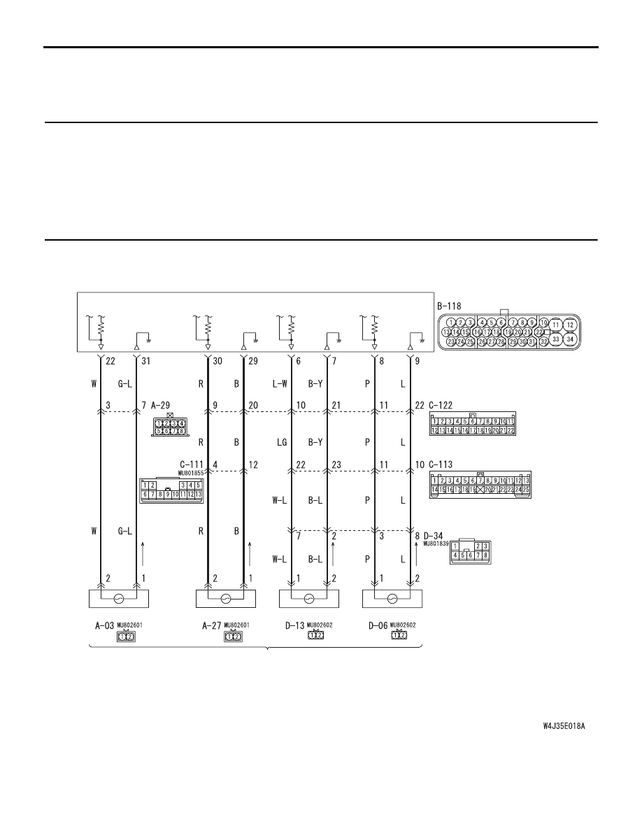
Code No.11: Front Right Wheel Speed Sensor (Open Circuit or Short Circuit)


Code No.12: Front Left Wheel Speed Sensor (Open Circuit or Short Circuit)


Code No.13: Rear Right Wheel Speed Sensor (Open Circuit or Short Circuit)


Code No.14: Rear Left Wheel Speed Sensor (Open Circuit or Short Circuit)


Code No.21: Front Right Wheel Speed Sensor System


Code No.22: Front Left Wheel Speed Sensor System


Code No.23: Rear Right Wheel Speed Sensor System


Code No.24: Rear Left Wheel Speed Sensor System

OPERATION

• A toothed wheel speed rotor generates a voltage 

pulse as it moves across the pickup field of each 
wheel speed sensor.

• The amount of voltage generated at each wheel 

is determined by the clearance between the 
wheel speed rotor teeth and the wheel speed 
sensor, and by the speed of rotation.

ABS-ECU

(FRONT: LH)

(FRONT: RH)

(REAR: LH)

(REAR: RH)

Wire colour code
B : Black     LG : Light green     G : Green     L : Blue     W : White     Y : Yellow     SB : Sky blue
BR : Brown     O : Orange     GR : Gray     R : Red     P : Pink     V : Violet

WHEEL SPEED SENSOR

Wheel Speed Sensor Circuit

TROUBLESHOOTING

ANTI-SKID BRAKING SYSTEM (ABS)

35B-12

• The wheel speed sensors transmit the frequency 

of the voltage pulses and the amount of voltage 
generated by each pulse to the ABS-ECU.

• The hydraulic unit modulates the amount of brak-

ing force individually applied to each wheel cylin-
der.

DIAGNOSIS CODE SET CONDITIONS

• Diagnosis codes 11, 12, 13, 14 are set when sig-

nal is not input due to breakage of the wires of 
one or more of the four wheel speed sensors.

• Diagnosis codes 21, 22, 23, 24 are set in the fol-

lowing cases:

• Open circuit is not found but no input is 

received by one or more of the four wheel 
speed sensors at 10 km/h or more.

• Sensor output drops due to a malfunctioning 

wheel speed sensor or warped wheel speed 
rotor.

PROBABLE CAUSES

The most likely causes for these diagnosis codes to 
set are:

Diagnosis codes 11, 12, 13, 14

• Malfunction of the wheel speed sensor

• Damaged wiring harness or connector

• Malfunction of the brake modulator hydraulic unit 

(integrated with ABS-ECU)

Diagnosis codes 21, 22, 23, 24

• Malfunction of the wheel speed sensor

• Damaged wiring harness or connector

• Malfunction of the brake modulator hydraulic unit 

(integrated with ABS-ECU)

• Malfunction of the wheel speed rotor

• Malfunction of the wheel bearing

• Excessive clearance between the wheel speed 

sensor and wheel speed rotor

DIAGNOSIS

STEP 1. M.U.T.-II/III data list.

CAUTION

To prevent damage to M.U.T.-II/III, always turn the 
ignition switch to the "LOOK" (OFF) position 
before connecting or disconnecting M.U.T.-II/III.

(1) Connect M.U.T.-II/III as shown in the illustration.
(2) Start the engine.
(3) Set M.U.T.-II/III to the data reading mode, and 

AC207179AB

M.U.T.-II

16-PIN

<Using the M.U.T.-II>

AC210056

AC

MB991911

16-PIN

MB991827

MB991824 

<Using the M.U.T.-III>

TROUBLESHOOTING

ANTI-SKID BRAKING SYSTEM (ABS)

35B-13

check the data list items by driving the vehicle.

• Item 11 (diagnosis code 11 or 21 is set): Front 

right wheel speed sensor

• Item 12 (diagnosis code 12 or 22 is set): Front 

left wheel speed sensor

• Item 13 (diagnosis code 13 or 23 is set): Rear 

right wheel speed sensor

• Item 14 (diagnosis code 14 or 24 is set): Rear 

left wheel speed sensor

OK: The reading on the speedometer 
nearly matches the indication on 
M.U.T.-II/III, when driving.

(4) Turn the ignition switch to the "LOCK" (OFF) 

position.

Q: Is the wheel speed sensor input normal?

YES : 

This malfunction is intermittent. Refer to 

GROUP 00, How to Use 
Troubleshooting/Inspection Service Points 

− 

How to Cope With Intermittent Malfunction 

P.00-5

NO : 

Go to Step 2.

STEP 2. Check the wheel speed sensor 
installation.

Q: Is the wheel speed sensor bolted securely in place 

at the front knuckle or the rear knuckle?
YES : 

Go to Step 3.

NO : 

Install it properly (Refer to 

P.35B-146

). Then 

go to Step 15     .

STEP 3. Inspect the wheel speed sensor and/or 
wheel speed rotor.
Refer to 

P.35B-147

.

Check items:

• Wheel speed sensor internal resistance: 1.24 − 

1.64 k

• Insulation between the wheel speed sensor body 

and the connector terminals

• Toothed wheel speed rotor check

Q: Is the wheel speed sensor or wheel speed rotor 

damaged?
YES : 

 Replace it (Refer to 

P.35B-146

). Then go to 

Step 15.

NO : 

Go to Step 4.

STEP 4. Check wheel speed sensor circuit. 
Resistance measurement at the ABS-ECU 
connector B-118.

(1) Disconnect the connector B-118 and measure at 

the harness side.

(2) Measure the resistance between the ABS-ECU 

connector terminals.

• If diagnosis code 11 or 21 is set: between ter-

minals 29 and 30

• If diagnosis code 12 or 22 is set: between ter-

minals 22 and 31

• If diagnosis code 13 or 23 is set: between ter-

minals 8 and 9

• If diagnosis code 14 or 24 is set: between ter-

minals 6 and 7

Standard Value: 1.24 

 1.64 k

Q: Is the resistance within the standard value?

YES : 

Go to Step 13.

NO <The resistance between terminals 22 and 31 is 
not within the standard value.> : 

Go to Step 5.

NO <The resistance between terminals 29 and 30 is 
not within the standard value.> : 

Go to Step 7.

NO <The resistance between terminals 6 and 7 is 
not within the standard value.> : 

Go to Step 9.

NO <The resistance between terminals 8 and 9 is 
not within the standard value.> : 

Go to Step 11.

AC212153

28

32

34

12

11

33

30

21

9

10

22

31

7

8

29

20 19

24

2

26

4

5

6

27

18 17

3

25

16 15

1

23

13

14

B-118 (B)

Connector: B-118

AB

Connector B-118
(harness side)

TROUBLESHOOTING

ANTI-SKID BRAKING SYSTEM (ABS)

35B-14

STEP 5. Check the following connectors.

ABS-ECU connector B-118

Intermediate connector A-29

Front wheel speed sensor (LH) connector A-03
Check the connectors for loose, corroded or dam-
aged terminals, or terminals pushed back in the con-
nector.

Q: Are the connectors and terminals in good 

condition?
YES : 

Go to Step 6.

NO : 

Repair it and then go to Step 15.

STEP 6. Check the following harness wires.

The wire between ABS-ECU connector B-118 (termi-

nal 22) and front wheel speed sensor (LH) con-
nector A-03 (terminal 2)

• The wire between ABS-ECU connector B-118 

(terminal 31) and front wheel speed sensor (LH) 
connector A-03 (terminal 1)

Q: Is any harness wire damaged?

YES : 

Repair or replace it and then go to Step 15.

NO : 

Go to Step 15.

AC211901AD

B-118 (B)

Connector: B-118

28

32

34

12

11

33

30

21

9

10

22

31

7

8

29

20 19

24

2

26

4

5

6

27

18 17

3

25

16 15

1

23

13

14

Harness side

AC211262 AX

Connector: A-29

A-29 (B)

6

2

5

1

8

7

3 4

AC211899AC

Connector: A-03

A-03 (B)

1

2

Harness side

AC211901AD

B-118 (B)

Connector: B-118

28

32

34

12

11

33

30

21

9

10

22

31

7

8

29

20 19

24

2

26

4

5

6

27

18 17

3

25

16 15

1

23

13

14

Harness side

AC211899AC

Connector: A-03

A-03 (B)

1

2

Harness side


Content   ..  493  494  495  496   ..