Mitsubishi Lancer Evolution IX. Manual - part 493
 

  Index      Mitsubishi     Mitsubishi Lancer Evolution IX - service repair manual


Search            


Content   ..  491  492  493  494   ..


Mitsubishi Lancer Evolution IX. Manual - part 493


SERVICE SPECIFICATIONS

ANTI-SKID BRAKING SYSTEM (ABS)

35B-3

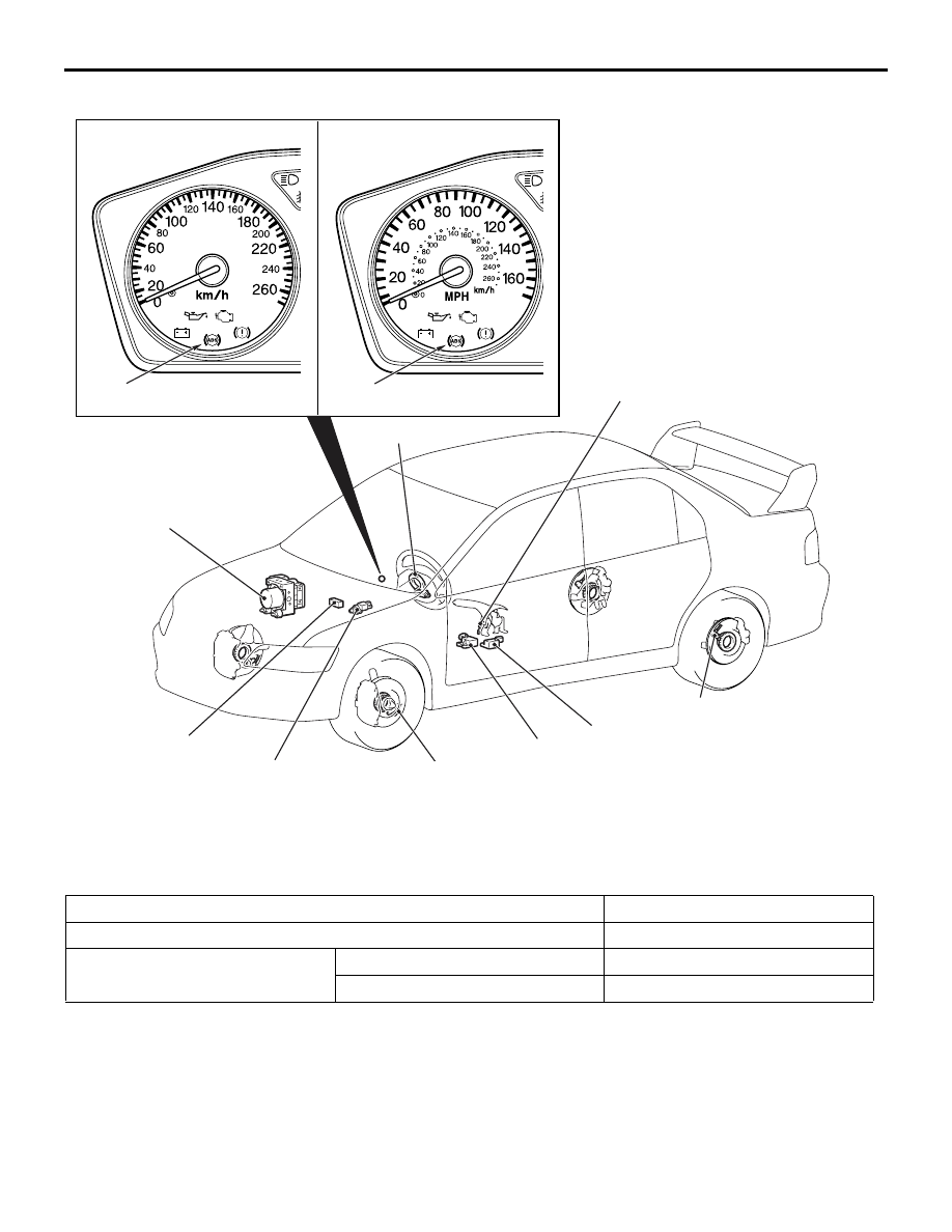
CONSTRUCTION DIAGRAM

SERVICE SPECIFICATIONS

M1352000300685

AC310670

Wheel speed sensor

AC

<R.H. drive vehicles>

<L.H. drive vehicles>

Wheel speed sensor

Lateral G-sensor

Longitudinal G-sensor

Steering wheel sensor

Stop lamp switch

Parking brake switch

Hydraulic unit and Brake
modulator (ABS-ECU)

ABS warning lamp

ABS warning lamp

Diagnosis connector

Item

Standard value

Wheel speed sensor internal resistance k

Ω  

1.24 

− 1.64

G-sensor output voltage V

Stationary Vehicles

2.4 

− 2.6

Arrow facing downward

3.4 

− 3.6

SPECIAL TOOLS

ANTI-SKID BRAKING SYSTEM (ABS)

35B-4

SPECIAL TOOLS

M1352000600794

Tool

Number

Name

Use

MB991502

M.U.T.-II sub assembly

Checking the ABS 
(Diagnosis display using 
the M.U.T.-II)

MB991955
A: MB991824
B: MB991827
C: MB991910
D: MB991911
E: MB991825
F: MB991826

M.U.T.-III sub-assembly
A: Vehicle communication 
interface (V. C. I).
B: M.U.T.-III USB cable
C: M.U.T.-III main 
harness A (Vehicles with 
CAN communication 
system)
D: M.U.T.-III main 
harness B (Vehicles 
without CAN 
communication system)
E: M.U.T.-III 
measurement adapter
F: M.U.T.-III trigger 
harness

Checking the ABS 
(Diagnosis display using 
the M.U.T.-III)

CAUTION

M.U.T.-III main harness 
B (MB991911) should be 
used. M.U.T.-III main 
harness A should not 
be used for this vehicle.

MB991529

Diagnosis code check 
harness

Checking the ABS 
(Diagnosis display using 
the ABS warning lamp)

B991502

MB991910

MB991826

MB991955

MB991911

MB991824

MB991827

MB991825

A

B

C

D

E

F

DO NOT USE

MB991529

TROUBLESHOOTING

ANTI-SKID BRAKING SYSTEM (ABS)

35B-5

TROUBLESHOOTING

STANDARD FLOW OF DIAGNOSTIC 
TROUBLESHOOTING

M1352011100641

Refer to GROUP 00, How to Use Troubleshoot-
ing/Inspection Service Points 

P.00-5

.

NOTES WITH REGARD TO DIAGNOSIS

M1352012600207

1. The ABS is a system which controls the brake 

pressure by means of the operation of the ECU. 
Accordingly, the following symptoms may occur at 
times, but these are a sign of normal ABS 
operation, and do not indicate a malfunction.

2. For road surfaces such as snow-covered roads 

and gravel roads, the braking distance for 
vehicles with ABS can sometimes be longer than 
that for other vehicles. Accordingly, advise the 
customer to drive safely on such roads by 
lowering the vehicle speed and not being too 
overconfident.

3. Diagnosis detection condition can vary depending 

on the diagnosis code. Make sure that checking 
requirements listed in the "Comment" are satisfied 
when checking the trouble symptom again.

MB991348 

Test harness set

Checking the G-sensor

Tool

Number

Name

Use

MB991348

Phenomenon

Explanation of phenomenon

When the engine starts, a knocking sound can be heard coming 
from the engine compartment.

This sound occurs as a result of system 
operation checking, and is not a 
malfunction.

• Sound of the motor inside the ABS hydraulic unit operation. 

(whine)

• Sound is the generated along with vibration of the brake 

pedal. (scraping)

• When ABS operates, sound is generated from the vehicle 

chassis due to repeated brake application and release. 
(Thump: suspension; squeak: tyres)

This is the sound of normal system 
operation, and is not a malfunction.

Shocks are felt if the brake pedal is depressed when driving at 
low speed.

This is due to system operation checking 
(starting-of check when the vehicle speed 
reaches a certain number of km/h) and is 
not a malfunction.

TROUBLESHOOTING

ANTI-SKID BRAKING SYSTEM (ABS)

35B-6

ABS WARNING LAMP INSPECTION

M1352012000249

Check that the ABS warning lamp illuminates as fol-
lows.
1. When the ignition switch is turned to the "ON" 

position, the ABS warning lamp illuminates for 
approximately 3 seconds and then switches off.

2. When the ignition switch is turned to the "START" 

position, the ABS warning lamp remains 
illuminated.

3. When the ignition switch is turned from the 

"START" position back to the "ON" position, the 
ABS warning lamp illuminates for approximately 3 
seconds and then switches off.
NOTE: The ABS waning lamp may remain on until 
the vehicle reaches a speed of several km/h. This 
is limited to cases where diagnosis code Nos. 21 
to 24, 41 to 44, or 53 to 55 have been recorded 
because of a previous problem occurring. In this 
case, the ABS-ECU keeps the warning lamp illu-
minated until the problem corresponding to that 
diagnosis code can be detected.

4. If the illumination is other than the above, check 

the diagnosis codes.

DIAGNOSIS FUNCTION

M1352011200819

READING DIAGNOSIS CODES
WHEN USING THE M.U.T.-II/III

Refer to GROUP 00, How to Use Troubleshoot-
ing/Inspection Service Points 

P.00-5

.

WHEN USING THE ABS WARNING LAMP

1. Turn the ignition switch to the "LOCK" (OFF) 

position.

2. Use special tool diagnosis code check harness 

(MB991529) to earth terminal number 1 
(diagnosis control terminal) of the diagnosis 
connector.

3. Turn the ignition switch to the "ON" position.

AC311051 AB

Approx. 3 s

Approx. 3 s

ABS
warning
lamp

Ignition
switch

Illuminated

Not
illuminated

START

ON

ACC

<L.H. drive vehicles>

<R.H. drive vehicles>

AC211895

1

2

3

4

5

6

7

8

9 10 11 12 13 14 15 16

AB

MB991529

Diagnosis connector


Content   ..  491  492  493  494   ..