Mitsubishi Lancer Evolution IX. Manual - part 496
 

  Index      Mitsubishi     Mitsubishi Lancer Evolution IX - service repair manual


Search            


Content   ..  494  495  496  497   ..


Mitsubishi Lancer Evolution IX. Manual - part 496


TROUBLESHOOTING

ANTI-SKID BRAKING SYSTEM (ABS)

35B-15

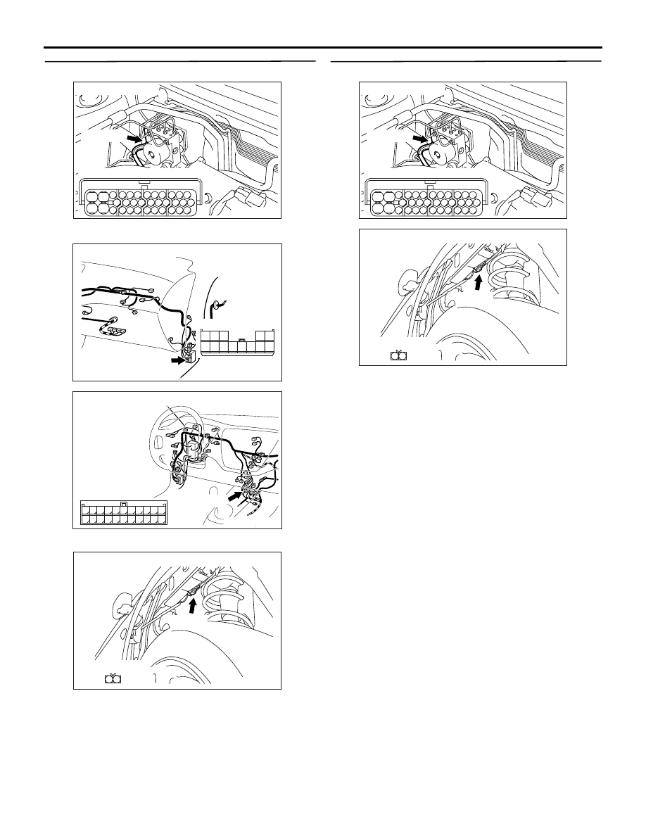
STEP 7. Check the following connectors.

ABS-ECU connector B-118

Intermediate connectors C-111, C-122 

Front wheel speed sensor (RH) connector A-27
Check the connectors for loose, corroded or dam-
aged terminals, or terminals pushed back in the con-
nector.

Q: Are the connectors and terminals in good 

condition?
YES : 

Go to Step 8.

NO : 

Repair it and then go to Step 15.

STEP 8. Check the following harness wires.

The wire between ABS-ECU connector B-118 (termi-

nal 29) and front wheel speed sensor (RH) con-
nector A-27 (terminal 1)

• The wire between ABS-ECU connector B-118 

(terminal 30) and front wheel speed sensor (RH) 
connector A-27 (terminal 2)

Q: Is any harness wire damaged?

YES : 

Repair or replace it and then go to Step 15.

NO : 

Go to Step 15.

AC211901AD

B-118 (B)

Connector: B-118

28

32

34

12

11

33

30

21

9

10

22

31

7

8

29

20 19

24

2

26

4

5

6

27

18 17

3

25

16 15

1

23

13

14

Harness side

AC211266

Connector: C-111

BN

Harness side

5 4 3

2 1

13121110 9 8 7 6

AC211265 DD

Connector: C-122

C-122 (L)

2

1

3

13

12

14

21

10

5

4

6

16

15

17

7 8 9

19

18

20

11

22

AC211900 AC

Connector: A-27

A-27 (B)

1

2

Harness side

AC211901AD

B-118 (B)

Connector: B-118

28

32

34

12

11

33

30

21

9

10

22

31

7

8

29

20 19

24

2

26

4

5

6

27

18 17

3

25

16 15

1

23

13

14

Harness side

AC211900 AC

Connector: A-27

A-27 (B)

1

2

Harness side

TROUBLESHOOTING

ANTI-SKID BRAKING SYSTEM (ABS)

35B-16

STEP 9. Check the following connectors.

ABS-ECU connector B-118

Intermediate connectors C-113, C-122, D-34 

• Rear wheel speed sensor (LH) connector D-13

Check the connectors for loose, corroded or dam-
aged terminals, or terminals pushed back in the con-
nector.

Q: Are the connectors and terminals in good 

condition?
YES : 

Go to Step 10.

NO : 

Repair it and then go to Step 15.

STEP 10. Check the following harness wires.

The wire between ABS-ECU connector B-118 (termi-

nal 6) and rear wheel speed sensor (LH) connec-
tor D-13 (terminal 1)

• The wire between ABS-ECU connector B-118 

(terminal 7) and rear wheel speed sensor (LH) 
connector D-13 (terminal 2)

Q: Is any harness wire damaged?

YES : 

Repair or replace it and then go to Step 15.

NO : 

Go to Step 15.

AC211901AD

B-118 (B)

Connector: B-118

28

32

34

12

11

33

30

21

9

10

22

31

7

8

29

20 19

24

2

26

4

5

6

27

18 17

3

25

16 15

1

23

13

14

Harness side

AC211266

Connector: C-113

BO

Harness side

16

3

14

1

15

2

17

4

18

5

20

8

19

6

7

21

9

22

10

13

2524

12

23

11

AC211265 DD

Connector: C-122

C-122 (L)

2

1

3

13

12

14

21

10

5

4

6

16

15

17

7 8 9

19

18

20

11

22

AC211902

AD

Connectors: D-13, D-34

D-34

D-13 (B)

Connector D-13
(Harness side)

1 2

Connector D-34

8

3

1

4 5 6

2

7

AC211901AD

B-118 (B)

Connector: B-118

28

32

34

12

11

33

30

21

9

10

22

31

7

8

29

20 19

24

2

26

4

5

6

27

18 17

3

25

16 15

1

23

13

14

Harness side

AC211902

AE

Connector: D-13

D-13 (B)

Harness side

1 2

TROUBLESHOOTING

ANTI-SKID BRAKING SYSTEM (ABS)

35B-17

STEP 11. Check the following connectors.

ABS-ECU connector B-118

Intermediate connectors C-113, C-122, D-34 

• Rear wheel speed sensor (RH) connector D-06

Check the connectors for loose, corroded or dam-
aged terminals, or terminals pushed back in the con-
nector.

Q: Are the connectors and terminals in good 

condition?
YES : 

Go to Step 12.

NO : 

Repair it and then go to Step 15.

STEP 12. Check the following harness wires:

The wire between ABS-ECU connector B-118 (termi-

nal 8) and rear wheel speed sensor (RH) connec-
tor D-06 (terminal 1)

• The wire between ABS-ECU connector B-118 

(terminal 9) and rear wheel speed sensor (RH) 
connector D-06 (terminal 2)

Q: Is any harness wire damaged?

YES : 

Repair or replace it and then go to Step 15.

NO : 

Go to Step 15.

STEP 13. Measure the wheel speed sensor 
output voltage.
Refer to 

P.35B-138

.

Output Voltage:

• When measured with a voltmeter: 42 mV or more

• When measured with an oscilloscope (maximum 

voltage): 120 mV or more

Q: Does the voltage meet the specification?

YES : 

Replace the brake modulator hydraulic unit 

(integrated with ABS-ECU) (Refer to 

P.35B-143

). Then go to Step 15.

NO : 

Go to Step 14.

AC211901AD

B-118 (B)

Connector: B-118

28

32

34

12

11

33

30

21

9

10

22

31

7

8

29

20 19

24

2

26

4

5

6

27

18 17

3

25

16 15

1

23

13

14

Harness side

AC211266

Connector: C-113

BO

Harness side

16

3

14

1

15

2

17

4

18

5

20

8

19

6

7

21

9

22

10

13

2524

12

23

11

AC211265 DD

Connector: C-122

C-122 (L)

2

1

3

13

12

14

21

10

5

4

6

16

15

17

7 8 9

19

18

20

11

22

AC211902

AF

Connectors: D-06, D-34

D-06 (B)

D-34

Connector D-06
(Harness side)

1 2

Connector D-34

8

3

1

4 5 6

2

7

AC211901AD

B-118 (B)

Connector: B-118

28

32

34

12

11

33

30

21

9

10

22

31

7

8

29

20 19

24

2

26

4

5

6

27

18 17

3

25

16 15

1

23

13

14

Harness side

AC211902

AG

Connector: D-06

D-06 (B)

Harness side

1 2

TROUBLESHOOTING

ANTI-SKID BRAKING SYSTEM (ABS)

35B-18

STEP 14. Check the wheel bearing.
Refer to GROUP 26, On-vehicle Service 

− Wheel 

Bearing Axial Play Check <Front>

P.26-6

 or GROUP 

27, On-vehicle Service 

− Wheel Bearing Axial Play 

Check <Rear>

P.27-30

. If play on the wheel bearing 

is not within the limit, replace the wheel bearing.

Limit: 0.05 mm

Q: Is play on the wheel bearing within the standard 

value?
YES : 

Go to Step 15.

NO : 

Replace it and then go to Step 15.

STEP 15. Check whether the diagnosis code is 
reset.

Check again if the diagnosis code is set.
(1) Turn the ignition switch to the "ON" position.
(2) Erase the diagnosis code.
(3) Turn the ignition switch to the "LOCK" (OFF) 

position.

(4) Turn the ignition switch to the "ON" position.
(5) Check if the diagnosis code is set.
(6) Turn the ignition switch to the "LOCK" (OFF) 

position.

Q: Do the diagnosis codes 11, 12, 13, 14, 21, 22, 23 or 

24 reset?
YES : 

Go to Step 1.

NO : 

The procedure is complete.

AC207179AB

M.U.T.-II

16-PIN

<Using the M.U.T.-II>

AC210056

AC

MB991911

16-PIN

MB991827

MB991824 

<Using the M.U.T.-III>


Content   ..  494  495  496  497   ..