Mitsubishi Lancer Evolution IX. Manual - part 373
 

  Index      Mitsubishi     Mitsubishi Lancer Evolution IX - service repair manual


Search            


Content   ..  371  372  373  374   ..


Mitsubishi Lancer Evolution IX. Manual - part 373


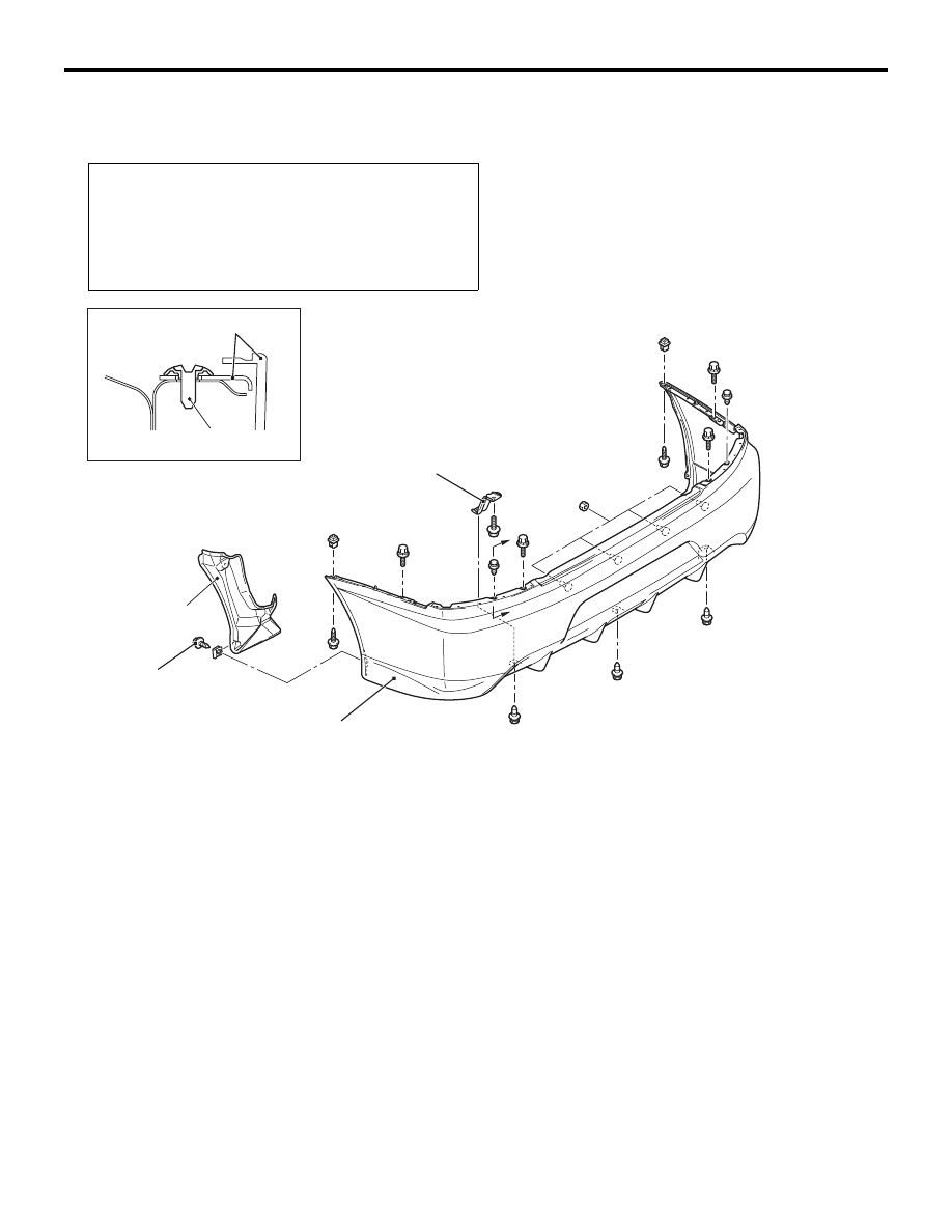
REAR BUMPER ASSEMBLY

EXTERIOR

51-5

REAR BUMPER ASSEMBLY

REMOVAL AND INSTALLATION

M1511001901011

Pre-removal and Post-installation Operation
• Rear Combination Lamp Removal and Installation (Refer 

to GROUP 54A, Rear Combination Lamp 

P.54A-67

.)

• Rear End Trim Removal and Installation (Refer to 

GROUP 52A, Trims 

P.52A-10

.)

• Trunk Room Side Trim Lid Removal and Installation 

(Refer to GROUP 52A, Trims 

P.52A-10

.)

AC504546

Splash shield

Clip

AB

3

2

3

1

A

A

Section A – A

Removal steps 
1. Splash shield mounting screw

2. Rear bumper bracket
3. Rear bumper assembly

Removal steps (Continued)

REAR BUMPER ASSEMBLY

EXTERIOR

51-6

DISASSEMBLY AND REASSEMBLY

M1511002100639

AC407263

AC504547

1

9

3

4

10

N

5

N

6

N

2

N

8

7

AB

Disassembly steps 

<<

A

>> >>

A

<< 1. Rivets A

<<

A

>> >>

A

<< 2. Rivets B

Licence plate lamp assembly

3. Rear bumper face support side 

reinforcement

4. Rear bumper under cover

5. Clip A
6. Clip B
7. Licence plate lamp bracket
8. Rear bumper reinforcement
9. Rear bumper side plate
10. Rear bumper face

Disassembly steps (Continued)

REAR BUMPER ASSEMBLY

EXTERIOR

51-7

DISASSEMBLY SERVICE POINT
<<A>> RIVETS A AND B REMOVAL

AC100411AB

Rivet

Drill

Bumper face

Use a drill (4.0 mm) to make a hole in the rivet to 
break it, and then remove the rivet.

ASSEMBLY SERVICE POINT
>>A<< RIVETS A AND B ASSEMBLY

Y0412AU

AC005876

18E0192

AE

1

2

3

4

Portion A

Rivet

Flange

Rivet

Rear bumper

side plate

Rear bumper
face

Rear bumper face

Rivet tool

Rivet tool

Use the rivet tool shown in the illustration to attach 
the rivet by the following procedures.
1. Insert the rivet into the rear bumper face and rear 

bumper side plate.

2. Place the rivet tool over portion A of the rivet.
3. While pushing the flange surface of the rivet with 

the rivet tool, press the handle of the tool.

4. The thin part of portion A is cut out and the rivet is 

held in position.

SIDE AIR DAM

EXTERIOR

51-8

SIDE AIR DAM

ADHESIVE

M1511000500932

Item

Specification

Side air dam

Double-sided tape: General products 
5 mm width and 1.2 mm thickness

REMOVAL AND INSTALLATION

M1511005500153

AC310080 AB

Adhesive tape: double-sided tape [ 5 mm width and 1.2 mm thickness ]

A

A

1

Section A – A

Clip

1

1

REMOVAL 

<<

A

>> >>

A

<< 1. Side air dam


Content   ..  371  372  373  374   ..