Mitsubishi Lancer Evolution IX. Manual - part 336
 

  Index      Mitsubishi     Mitsubishi Lancer Evolution IX - service repair manual


Search            


Content   ..  334  335  336  337   ..


Mitsubishi Lancer Evolution IX. Manual - part 336


AC407431

N

9

9.0 ± 1.0 N·m

<Cold engine>
78 ± 2 N·m to 0 N·m to 
20 ± 2 N·m to 
+90˚ to +90˚

31 ± 3 N·m

5.0 ± 1.0 N·m

35 ± 6 N·m

14 ± 1 N·m

30 ± 3 N·m

11 ± 1 N·m

30 ± 3 N·m

42 ± 2 N·m

11

12

13

14

15

16

17

18

19

20

21

22

23

24

25

26

27

28

29

32

31

AC

N

N

N

20 ± 2 N·m

N

N

N

N

30

(Engine oil)

(Engine oil)

10

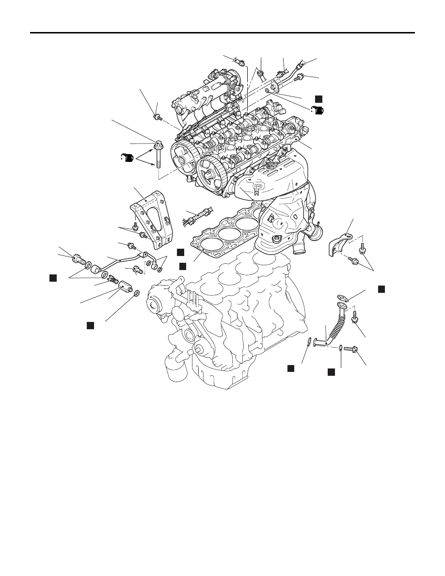
Removal steps 

9.

Alternator brace bolt

10. Battery wiring harness connection
11. Inlet manifold stay

>>

E

<<

12. Eye bolt
13. Gasket
14. Eye bolt
15. Gasket
16. Oil feeder control valve pipe
17. Filter
18. Oil pipe joint
19. Gasket
20. Gasket
21. Oil return tube
22. Oil return tube gasket

>>

D

<<

23. Oil return tube gasket

24. Turbocharger bracket

Water outlet fitting and thermostat 
case assembly (Refer to GROUP 
14, Water Hose and Water Pipe 

P.14-22

).

Rocker cover (Refer to 

P.11A-17

).

25. Water return hose connection
26. Heater hose connection 
27. Fuel return line hose connection 

>>

C

<<

28. Fuel high-pressure hose 

connection

>>

C

<<

29. O-ring

<<

A

>>

>>

B

<<

30. Cylinder head bolts
31. Cylinder head assembly

>>

A

<<

32. Cylinder head gasket

CYLINDER HEAD GASKET

ENGINE MECHANICAL

11A-33

Removal steps (Continued)

CYLINDER HEAD GASKET

ENGINE MECHANICAL

11A-34

REMOVAL SERVICE POINT
<<A>> CYLINDER HEAD BOLTS 
REMOVAL

AC201623 

MB991654

Engine front

1

2

4

6

9

7

3

5

10

8

AB

Using special tool cylinder head bolt wrench 
(MB991654), loosen the cylinder head bolts in two or 
three steps in the order shown in the illustration.
NOTE: If the cylinder head bolts cannot be pulled out 
due to the washer being trapped in the valve spring, 
raise the bolt slightly, then remove it while holding it 
by using a magnet.

INSTALLATION SERVICE POINTS
>>A<< CYLINDER HEAD GASKET 
INSTALLATION

CAUTION

Do not allow any foreign materials to get into the 
coolant passages, oil passages and cylinder.
1. Remove the gasket from the cylinder head and 

cylinder block.

AC107217AC

Identification
mark "63"

Exhaust side

2. Assemble to the cylinder block so the cylinder 

head gasket identification mark "63" is at the top 
surface and on the exhaust side.

>>B<< CYLINDER HEAD BOLTS 
INSTALLATION

AC102537

A

AB

(Engine oil)

1. Check that the nominal length of each cylinder 

head bolt meets the limit. If it exceeds the limit, 
replace the bolt with a new one.

Limit (A): 99.4 mm

2. Apply a small amount of engine oil to the thread of 

the bolts and to the washers.

AC201625 

MB991654

10

9

7

5

2

4

8

6

1

3

Engine front

AB

3. Use special tool cylinder head bolt wrench 

(MB991654) to tighten the cylinder head bolts as 
follows:
(1) Tighten the cylinder head bolts to 78 

± 2 N⋅m 

in the order shown.

(2) Loosen the bolts fully in the reverse order of 

that shown.

CYLINDER HEAD GASKET

ENGINE MECHANICAL

11A-35

(3) Tighten the cylinder head bolts to 20 

± 2 N⋅m 

in the order shown.

AC102331AB

Paint marking

90˚

90˚ 

Step (4)

Step (5)

Paint marking

(4) Apply a paint mark to the heads of the cylinder 

head bolts and cylinder head, then tighten 90 
degree angle as shown.

CAUTION

The bolt is not tightened sufficiently if the bolt is 
tightened less than 90 degree angle.

(5) Tighten the bolt an additional 90 degree angle 

as shown. Then check to see that the paint 
mark on the head of the cylinder head bolts 
and the paint mark on the cylinder head are 
aligned.

(6) If tightening the bolt 90 degree angle results in 

moving the paint mark on the bolt past the 
paint mark on the cylinder head, remove the 
bolt and start over from step 1.

>>C<< O-RING/FUEL HIGH-PRESSURE 
HOSE INSTALLATION

CAUTION

Do not let any engine oil get into the delivery 
pipe.
1. Apply a small amount of new engine oil to the 

O-ring.

2. Turning the fuel high-pressure hose to the right 

and left, install it onto the delivery pipe, while 
being careful not to damage the O-ring. After 
installing, check that the hose turns smoothly.

3. If the hose does not turn smoothly, the O-ring is 

probably being clamped. Disconnect the fuel 
high-pressure hose and check the O-ring for 
damage. After this, re-insert it to the delivery pipe 
and check that the hose turns smoothly.

4. Tighten the fuel high-pressure hose mounting 

bolts to the specified torque.

Tightening torque: 5.0 

± 1.0 Nm

>>D<< OIL RETURN TUBE GASKET 
INSTALLATION

AC211005 AB

Convex part

The oil return tube gasket should be replaced with a 
new one.  Set the convex part to the position shown 
in the illustration.
NOTE: There is no specific direction indicated for 
installing the turbocharger side of the oil return tube 
gasket.

>>E<< EYE BOLT INSTALLATION

CAUTION

When tightening the eye bolt, hold the oil pipe 
joint with a spanner so that it does not rotate with 
the eye bolt.

TIMING BELT

ENGINE MECHANICAL

11A-36

TIMING BELT

REMOVAL AND INSTALLATION

M1112004301400

CAUTION

If the vehicle is equipped with the Brembo

 disc brake, during maintenance, take care not to contact 

the parts or tools to the caliper because the paint of caliper will be scratched.

Pre-removal Operation
• Under Cover Removal (Refer to GROUP 51, Front 

Bumper 

P.51-2

).

• Side Cover Removal

• Crankshaft Shaft Damper Pulley Removal (Refer to 

P.11A-15

).

• Front Axle Crossmember Bar Removal (Refer to GROUP 

32, Engine Roll Stopper and Centermember 

P.32-7

).

• Front Exhaust Pipe Removal (Refer to GROUP 15, 

Exhaust Pipe and Main Muffler 

P.15-13

).

Post-installation Operation
• Front Exhaust Pipe Installation (Refer to GROUP 15, 

Exhaust Pipe and Main Muffler 

P.15-13

).

• Front Axle Crossmember Bar Installation (Refer to 

GROUP 32, Engine Roll Stopper and Centermember 

P.32-7

).

• Crankshaft Shaft Damper Pulley Installation (Refer to 

P.11A-15

).

• Drive Belt Tension Check (Refer to 

P.11A-7

).

• Side Cover Installation

• Under Cover Installation (Refer to GROUP 51, Front 

Bumper 

P.51-2

).

AC406655AC

2

11 ± 1 N·m

3

4

5

6

7

8

9

10

11 ± 1 N·m

9.0 ± 1.0 N·m

23 ± 3 N·m

48 ± 5 N·m

8.8 ± 1.0 N·m

44 ± 10 N·m

79 ± 5 N·m

21 ± 4 N·m

24 ± 4 N·m

1

12 ± 2 N·m

Removal steps 

1.

Power steering pressure hose 
connection

2.

Timing belt upper cover

3.

Water pump pulley

4.

Idler pulley

5.

Auto-tensioner

6.

Timing belt lower cover

Engine mounting insulator (Refer to 
GROUP 32, Engine Mount 

P.32-4

).

>>

G

<< •

Valve timing belt tension 
adjustment

<<

A

>>

>>

F

<<

7.

Valve timing belt

>>

E

<<

8.

Timing belt tensioner pulley

9.

Timing belt tensioner arm

>>

D

<<

10. Timing belt tensioner adjuster

Removal steps (Continued)


Content   ..  334  335  336  337   ..