Mitsubishi Lancer Evolution IX. Manual - part 337
 

  Index      Mitsubishi     Mitsubishi Lancer Evolution IX - service repair manual


Search            


Content   ..  335  336  337  338   ..


Mitsubishi Lancer Evolution IX. Manual - part 337


AC211076

(Engine oil)

35 ± 6 N·m
  

19 ± 3 N·m
  

167 N·m
  

8.8 ± 1.0 N·m

17

16

15

20

18

19

22 ± 4 N·m
  

49 ± 9 N·m

49 ± 9 N·m

40 ± 5 N·m

22 ± 4 N·m
  

11

12

13

14

12 ± 2 N·m

AD

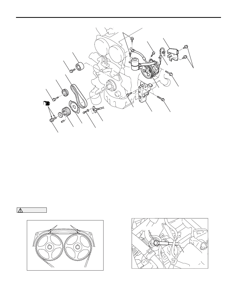
Removal steps 

11. Power steering pressure switch 

connector

12. Power steering oil pump heat 

protector

<<

B

>>

13. Power steering oil pump, bracket 

and reservoir assembly

14. Power steering oil pump bracket

15. Timing belt Idler pulley
16. Crank angle sensor

<<

C

>>

>>

C

<<

17. Crankshaft camshaft drive sprocket

>>

C

<<

18. Crankshaft angle sensing blade

>>

B

<<

Balancer timing belt tension 
adjustment

>>

A

<<

19. Balancer timing belt tensioner

<<

D

>>

>>

A

<<

20. Balancer timing belt

TIMING BELT

ENGINE MECHANICAL

11A-37

REMOVAL SERVICE POINTS
<<A>> VALVE TIMING BELT REMOVAL

CAUTION

Never turn the crankshaft anti-clockwise.

AC102487

Timing mark

AC

1. Turn the crankshaft clockwise, align each timing 

mark to set No.1 cylinder to TDC of its 
compression stroke.

AC211534AB

MD998738

Timing belt
under cover

2. Remove the timing belt under cover rubber plug 

and then set the special tool adjusting bolt 
(MD998738).

Removal steps (Continued)

AC107289

MD998738

Timing belt
tensioner arm

AB

TIMING BELT

ENGINE MECHANICAL

11A-38

3. Screw in the special tool until it comes in contact 

with the timing belt tensioner arm.

CAUTION

The special tool can be gradually installed at a 
rate of a 30 degree turn per second. If it is 
screwed in all at once, the timing belt tensioner 
adjuster rod will not easily retract and the special 
tool may bend.

AC102775AB

A

B

4. Gradually screw in the special tool. Then align the 

timing belt tensioner adjuster rod set hole A with 
the timing belt tensioner adjustor cylinder set hole 
B.

AC107185AC

Wire or pin

Timing belt 
tensioner pulley
mounting bolt 

5. Insert a wire or pin in the set hole.

CAUTION

For reinstallation of the valve timing belt, draw an 
arrow indicating the rotating direction (clock-
wise) on the back of the belt using chalk.
6. After removal of the special tool, loosen the timing 

belt tensioner pulley mounting bolt and remove 
the valve timing belt.

<<B>> POWER STEERING OIL PUMP, 
BRACKET AND RESERVOIR ASSEMBLY 
REMOVAL

With the hose installed, remove the power steering 
oil pump assembly from the bracket.
NOTE: Secure the removed power steering oil pump 
assembly with cord or rope at a position where they 
will not interfere with the removal of the balancer tim-
ing belt.

<<C>> CRANKSHAFT CAMSHAFT DRIVE 
SPROCKET REMOVAL

AC102332AB

MB991385

MB991367

Crankshaft
camshaft
drive 
sprocket

1. Use the following special tools to support the 

crankshaft camshaft drive sprocket.

• Special spanner (MB991367)

• Pin (MB991385)

2. Loosen the crankshaft pulley centre bolt and 

remove the crankshaft camshaft drive sprocket.

<<D>> BALANCER TIMING BELT 
REMOVAL

CAUTION

For reinstallation of the balancer timing belt, 
draw an arrow indicating the rotating direction 
(clockwise) on the back of the belt using chalk.

TIMING BELT

ENGINE MECHANICAL

11A-39

INSTALLATION SERVICE POINTS
>>A<< BALANCER TIMING BELT/BAL-
ANCER TIMING BELT TENSIONER 
INSTALLATION

AC102689AB

Balancershaft sprocket

Belt tension side

Timing mark

Timing mark

Crankshaft
balancershaft
drive sprocket

1. Ensure that the crankshaft balancershaft drive 

sprocket timing marks and balancershaft sprocket 
timing marks are aligned.

2. Install the balancer timing belt on the crankshaft 

balancershaft drive sprocket and balancershaft 
sprocket. There should be no slack on the tension 
side.

AC102690 AB

Centre of
the pulley

Centre of the 
mounting bolt

3. Assemble and temporarily fix the centre of the 

pulley of the balancer timing belt tensioner so that 
it is at the top left from the centre of the 
assembling bolt, and the pulley flange is at the 
front-side of the engine.

4. Adjust the balancer timing belt tension.

>>B<< BALANCER TIMING BELT 
TENSION ADJUSTMENT 

CAUTION

When tightening the mounting bolts, ensure that 
the tensioner does not rotate with the bolts. 
Allowing it to rotate with the bolts can cause 
excessive tension of the belt.

AC102691AB

Belt tension side

1. With your fingers, lift the balancer timing belt 

tensioner in the direction of the arrow. Apply 
pressure of 3.0 

± 0.4 N⋅m to the balancer timing 

belt. Tighten the assembling bolt to the standard 
torque. Then, fix the balancer timing belt 
tensioner.

Tightening torque: 19 

± 3 Nm

AC102689AC

Balancershaft sprocket

Timing mark

Timing mark

Crankshaft
balancershaft
drive sprocket

2. Turn the crankshaft clockwise two turns to set 

No.1 cylinder to TDC of its compression stroke 
and check that the sprocket timing marks are 
aligned.

AC102693AB

Deflection

Approximately 100 N

TIMING BELT

ENGINE MECHANICAL

11A-40

3. Apply a pressure of approximately 100N at the 

centre (arrow area) between the sprocket as 
shown, then inspect whether the belt deflection is 
within the standard value.

Standard value:

At adjustment: 5 

 7 mm

At replacement: 5 

 7 mm

4. If not within the standard value, adjust the belt 

tension again.

>>C<< CRANKSHAFT ANGLE SENSING 
BLADE/CRANKSHAFT CAMSHAFT 
DRIVE SPROCKET INSTALLATION

AC211535AC

Crankshaft camshaft 
drive sprocket

Crankshaft pulley 
centre bolt

Crankshaft

Crankshaft angle 
sensing blade

Crankshaft 
pulley washer

Engine front

: Clean
: Clean and degrease
: Apply engine oil

1. Clean or degrease the crankshaft, the crankshaft 

angle sensing blade, the crankshaft camshaft 
drive sprocket and crankshaft pulley washer as 
shown.
NOTE: Also clean the degreased surfaces.

2. Install the crankshaft angle sensing blade and 

crankshaft camshaft drive sprocket in the direction 
shown.

3. Place the larger chamfer side of the crank shaft 

pulley washer in the direction shown and then 
assemble on the crankshaft pulley centre bolt.

4. Apply some engine oil to the crankshaft pulley 

centre bolt bearing surface and screw.

AC102332AB

MB991385

MB991367

Crankshaft
camshaft
drive 
sprocket

5. Use the following special tool as during removal to 

support the crankshaft camshaft drive sprocket.

• Special spanner (MB991367)

• Pin (MB991385)

6. Tighten the crankshaft pulley centre bolts to the 

specified torque.

Tightening torque: 167 N

m

>>D<< TIMING BELT TENSIONER 
ADJUSTER INSTALLATION

1. Install according to the following procedures when 

the timing belt tensioner adjuster rod is fully 
extended.

CAUTION

If the compression is too fast, the procedure may 
damage the rod.

AC102334AB

A

B

(1) Slowly compress the timing belt tensioner 

adjuster rod using a press or vice, then align 
the set hole A of the rod with set hole B of the 
timing belt tensioner adjuster cylinder.


Content   ..  335  336  337  338   ..