Mitsubishi Lancer Evolution IX. Manual - part 334
 

  Index      Mitsubishi     Mitsubishi Lancer Evolution IX - service repair manual


Search            


Content   ..  332  333  334  335   ..


Mitsubishi Lancer Evolution IX. Manual - part 334


CAMSHAFT AND VALVE STEM SEAL

ENGINE MECHANICAL

11A-25

2. Install the vane (small) of the camshaft position 

sensing cylinder at an angle of approximately 45 
degrees to the position of the dowel pin of the 
exhaust camshaft.

3. Tighten the camshaft position sensing cylinder 

mounting bolts to the specified torque.

Tightening torque: 22 

± 4 Nm

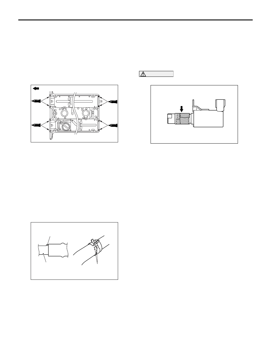
>>M<< ROCKER COVER INSTALLATION

AC201469

Engine front

AC

1. Apply sealant to the positions of the rocker cover 

gasket (8 areas) as shown in the illustration.

Specified sealant: MITSUBISHI GENUINE 
PART MD970389 or equivalent

2. Install the rocker cover to the cylinder head.
3. Tighten the rocker cover mounting bolts to the 

specified torque.

Tightening torque: 3.5 

± 0.5 Nm

>>N<< RADIATOR UPPER HOSE 
CONNECTION

AC200642

Mating marks

Projection

Water outlet fitting

AB

1. Insert each hose until it contacts the projection on 

the water outlet fitting.

2. Align the mating marks on the radiator hose and 

hose clamp, and then secure the radiator hose.

>>O<< O-RING/OIL FEEDER CONTROL 
VALVE INSTALLATION

CAUTION

• Never re-use the O-ring.

AC504840AB

Tape

Before installing O-ring, wind the tape with the 

soft adhesion (sealing tape) around the oil 
passages cut-out area of engine oil control 
valve to prevent the damage. If the O-ring is 
damaged, it can be the cause of oil leak.

1. Apply a small amount of engine oil to the O-ring 

and then install it to the oil control valve.

2. Assemble the engine oil control valve to the 

cylinder head.

3. Tighten the engine oil control valve mounting bolt 

to the specified torque.

Tightening torque: 11 

± 1 Nm

OIL PAN

ENGINE MECHANICAL

11A-26

OIL PAN

REMOVAL AND INSTALLATION

M1112002801409

Pre-removal Operation
• Under Cover Removal (Refer to GROUP 51, Front 

Bumper 

P.51-2

).

• Engine Oil Draining (Refer to GROUP 12, On-vehicle 

Service 

− Engine Oil Replacement 

P.12-3

).

• Front Axle Crossmember Bar Removal (Refer to GROUP 

32, Engine Roll Stopper and Centermember 

P.32-7

).

• Front Exhaust Pipe Removal (Refer to GROUP 15, 

Exhaust Pipe and Main Muffler 

P.15-13

).

• Starter Assembly Removal (Refer to GROUP 16, Starter 

Motor Assembly 

P.16-20

).

Post-installation Operation
• Starter Assembly Installation (Refer to GROUP 16, Starter 

Motor Assembly 

P.16-20

).

• Front Exhaust Pipe Installation (Refer to GROUP 15, 

Exhaust Pipe and Main Muffler 

P.15-13

).

• Front Axle Crossmember Bar Installation (Refer to 

GROUP 32, Engine Roll Stopper and Centermember 

P.32-7

).

• Engine Oil Refilling (Refer to GROUP 12, On-vehicle 

Service 

− Engine Oil Replacement 

P.12-3

).

• Under Cover Installation (Refer to GROUP 51, Front 

Bumper 

P.51-2

).

AC310566

N

9.0 ± 3.0 N·m

9.0 ± 3.0 N·m

26 ± 5 N·m

<Bolt, washer assembled>
9.0 ± 1.0 N·m
<Flange bolt>
10 ± 2 N·m

39 ± 5 N·m

2

3

1

AB

5

4

N

N

22 ± 4 N·m

42 ± 2 N·m

N

9.0 ± 1.0 N·m

14 ± 1 N·m

N

5.0 ± 1.0 N·m

8.8 ± 1.0 N·m

7

6

13

12

10

11

8

9

Removal steps 

1.

Flywheel housing front lower cover

2.

Gasket

3.

Oil return tube

4.

Oil return tube gasket

>>

C

<< 5.

Oil return tube gasket

6.

Engine oil level sensor connector

7.

Engine oil level sensor

8.

Engine oil cooler return hose

9.

Engine oil cooler tube gaskets

10. Engine oil pan drain plug

>>

B

<< 11. Engine oil pan drain plug gasket

<<

A

>> >>

A

<< 12. Engine oil pan

13. Cylinder block baffle plate

Removal steps (Continued)

OIL PAN

ENGINE MECHANICAL

11A-27

REMOVAL SERVICE POINT
<<A>> ENGINE OIL PAN REMOVAL

1. Remove the engine oil pan mounting bolts.

AC301325

A

B

AB

AC102324 AB

MD998727

MD998727

CAUTION

Do not use special tool oil pan FIPG cutter 
(MD998727) in area A of the engine oil pan. Using 
the special tool in area A may cause deformation 
of the front case because the front case is made 
of aluminium.
2. Tap the special tool into the range (B) between the 

cylinder block and the engine oil pan, and then 
slide the tool sideways.
NOTE: If any sounding parts interfere with the 
removal, there is no need to use the special tool.

3. Remove the engine oil pan.

INSTALLATION SERVICE POINTS
>>A<< ENGINE OIL PAN INSTALLATION

1. Remove old sealant from the engine oil pan and 

cylinder block surfaces.

AC211002

Groove
portion


4 mm

Bolt hole
portion

AB

2. Apply a bead of the sealant to the cylinder block 

mating surface of the engine oil pan as shown.

Specified sealant: MITSUBISHI GENUINE 
PART MD970389 or equivalent

NOTE: Install the engine oil pan within 15 minutes 
after applying sealant.

3. Assemble the engine oil pan to the cylinder block.

CAUTION

Wait at least one hour. Never start the engine or 
let engine oil or coolant touch the sealant surface 
during this time.

AC211004

M6 × 8 mm

AB

4. Tighten the engine oil pan mounting bolts to the 

specified torque. Be careful when installing, as the 
oil pan mounting bolts (indicated in the illustration) 
have different lengths from the other bolts.

Tightening torque: 9.0 

± 3.0 Nm

OIL PAN

ENGINE MECHANICAL

11A-28

>>B<< ENGINE OIL PAN DRAIN PLUG 
GASKET INSTALLATION

AC102325 AE

Engine 
oil pan 
side

Replace the gasket with a new gasket. Install the 
new gasket in the direction shown in the illustration.

>>C<< OIL RETURN TUBE GASKET 
INSTALLATION

AC211005 AB

Convex part

The oil return tube gasket should be replaced with a 
new one. Set the convex part to the position as 
shown in the illustration for installation.
NOTE: There is no specific direction indicated for 
installing the turbocharger side of the oil return tube 
gasket.

INSPECTION

M1112002900265

• Check the engine oil pan for cracks.

• Check the engine oil pan sealant-coated surface 

for damage and deformation.


Content   ..  332  333  334  335   ..