Mitsubishi Lancer Evolution IX. Manual - part 295
 

  Index      Mitsubishi     Mitsubishi Lancer Evolution IX - service repair manual


Search            


Content   ..  293  294  295  296   ..


Mitsubishi Lancer Evolution IX. Manual - part 295


INPUT SHAFT

MANUAL TRANSMISSION OVERHAUL

22B-25

DISASSEMBLY SERVICE POINTS
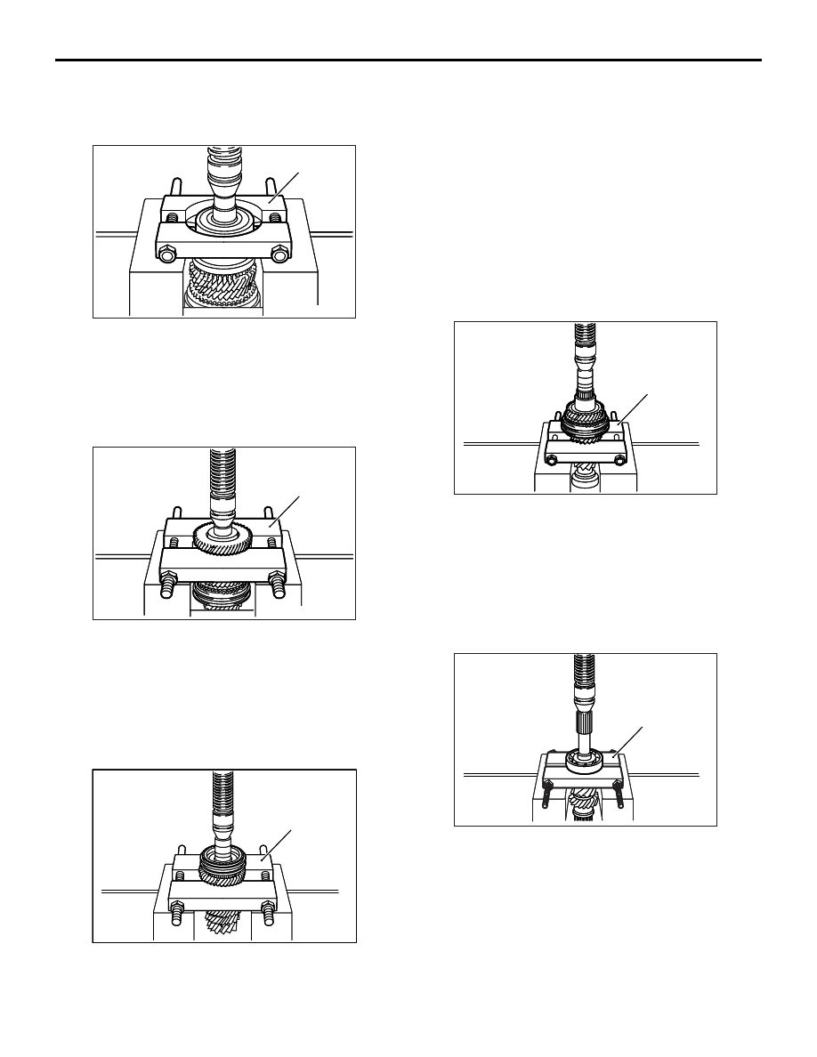
<<A>> INPUT SHAFT REAR BEARING 
REMOVAL

AK203338

AK203338AC

MD998801

Using the special tool Bearing remover (MD998801) 
to support the input shaft rear bearing, remove the 
bearing.

<<B>> 6TH GEAR SLEEVE / NEEDLE 
BEARING / 6TH GEAR REMOVAL

AK203339

AK203339

MD998917

AD

Using the special tool Bearing remover (MD998917) 
to support the 6th gear, remove the 6th gear sleeve, 
needle bearing, and 6th gear.

<<C>> 5TH-6TH SYNCHRONIZER 
ASSEMBLY / SYNCHRONIZER RING / 5TH 
GEAR REMOVAL

AK203340

AK203340

MD998917

AC

Using the special tool Bearing remover (MD998917) 
to support the 5th gear, remove the 5th-6th synchro-
nizer assembly, synchronizer ring, and 5th gear.

<<D>> 5TH GEAR SLEEVE / THRUST 
WASHER / 4TH GEAR / NEEDLE 
BEARING / 4TH GEAR SLEEVE / 3RD-4TH 
SYNCHRONIZER ASSEMBLY / 
SYNCHRONIZER OUTER RING / 
SYNCHRONIZER CONE / 
SYNCHRONIZER INNER RING / 3RD 
GEAR REMOVAL

AK203341

AK203341

MD998917

AC

Using the special tool Bearing remover (MD998917) 
to support the 3rd gear, remove the 5th gear sleeve, 
thrust washer, 4th gear, needle bearing, 4th gear 
sleeve, 3rd-4th synchronizer assembly, synchronizer 
outer ring, synchronizer cone, synchronizer inner 
ring, and 3rd gear.

<<E>> BALL BEARING REMOVAL

AK203342

AK203342

MD998801

AC

Using the special tool Bearing remover (MD998801) 
to support the ball bearing, remove the bearing.

INPUT SHAFT

MANUAL TRANSMISSION OVERHAUL

22B-26

REASSEMBLY SERVICE POINTS
>>A<< BALL BEARING INSTALLATION

AK203343

AK203343

MD998818

AC

MD998813

MD998812

Using the following special tools, install the ball bear-
ing.

• Installer cap (MD998812)

• Installer 100 (MD998813)

• Installer adapter (MD998818)

>>B<< 3RD-4TH SYNCHRONIZER HUB / 
SYNCHRONIZER KEY / SYNCHRONIZER 
SLEEVE / SYNCHRONIZER SPRING 
INSTALLATION

AK204333AC

4th gear side

3rd gear seide

Identification 
groove

Oil grooves 
(4 places)

Oil grooves 
(3 places)

CAUTION

The synchronizer hub is not reusable.
1. Assemble the 3rd-4th synchronizer hub and 

synchronizer sleeve together as shown in the 
illustration.

AK204334 AC

Center step

Center step

CAUTION

Install the synchronizer springs on the synchro-
nizer keys so that the center steps on both 
springs are not positioned on the same key.
2. Install the synchronizer keys and synchronizer 

springs as shown in the illustration.

>>C<< 3RD-4TH SYNCHRONIZER 
ASSEMBLY INSTALLATION

AK203344

AK203344

MD998823

AC

MD998813

MD998812

MD998801

CAUTION

When press fitting the synchronizer assembly 
onto the main shaft, make sure that the synchro-
nizer rings do not get caught in the hub.
Using the following special tools, install the 3rd-4th 
synchronizer assembly.

• Bearing remover (MD998801)

• Installer cap (MD998812)

• Installer 100 (MD998813)

• Installer adapter (MD998823)

>>D<< 4TH GEAR SLEEVE 
INSTALLATION

AK203345

AK203345

MD998822

AC

MD998813

MD998812

MD998801

Using the following special tools, install the 4th gear 
sleeve.

• Bearing remover (MD998801)

• Installer cap (MD998812)

• Installer 100 (MD998813)

• Installer adapter (MD998822)

INPUT SHAFT

MANUAL TRANSMISSION OVERHAUL

22B-27

>>E<< THRUST WASHER INSTALLATION

AK204344

AK204344AC

A

B

CAUTION

Do not use more than one thrust washer.
1. Select a washer that allows distance A in the 

illustration to fall within the standard value range.

Standard value: 167.6 

 167.7 mm

Selecting appropriate washer

a. Use a dial gauge to measure the distance 

between the 4th bearing sleeve and the front 
bearing (distance B in the illustration).

b. Select a washer that allows distance A to fall 

within the standard value range when the thick-
ness of the washer is added to the distance B 
measurement.

AK203346

AK203346

MD998822

AC

MD998813

MD998812

MD998801

2. Using the following special tools, install the thrust 

washer.

• Bearing remover (MD998801)

• Installer cap (MD998812)

• Installer 100 (MD998813)

• Installer adapter (MD998822)

>>F<< 5TH GEAR SLEEVE 
INSTALLATION

AK203347

AK203347

MD998822

AC

MD998813

MD998812

MD998801

Using the following tools, install the 5th gear sleeve.

• Bearing remover (MD998801)

• Installer cap (MD998812)

• Installer 100 (MD998813)

• Installer adapter (MD998822)

>>G<< 5TH-6TH SYNCHRONIZER HUB / 
SYNCHRONIZER KEYS / SYNCHRONIZER 
SLEEVE INSTALLATION

AK204171AC

6th gear seide

5th gear side

Oil grooves 
(4 places)

Oil grooves 
(3 places)

Identification
groove

CAUTION

The synchronizer hub is not reusable.
1. Assemble the 5th-6th synchronizer hub and 

synchronizer sleeve together as shown in the 
illustration.

AK204334 AC

Center step

Center step

2. Install the synchronizer keys and synchronizer 

springs as shown in the illustration.

INPUT SHAFT

MANUAL TRANSMISSION OVERHAUL

22B-28

>>H<< 5TH-6TH SYNCHRONIZER 
ASSEMBLY INSTALLATION

AK203348

AK203348

MD998822

AC

MD998813

MD998812

MD998801

CAUTION

When press fitting the synchronizer assembly 
onto the main shaft, make sure that the synchro-
nizer rings do not get caught in the hub.
Using the following special tools, install the 5th-6th 
synchronizer assembly.

• Bearing remover (MD998801)

• Installer cap (MD998812)

• Installer 100 (MD998813)

• Installer adapter (MD998822)

>>I<< 6TH GEAR SLEEVE INSTALLATION

AK203349

AK203349

MD998818

AC

MD998812

MD998801

Using the following special tools, install the 6th gear 
sleeve.

• Bearing remover (MD998801)

• Installer cap (MD998812)

• Installer adapter (MD998818)

>>J<< SNAP RING INSTALLATION

AK203350

Select a snap ring that allows the clearance between 
the snap ring and snap ring groove to fall within the 
standard value range.

Standard value: 0 

 0.1 mm

>>K<< INPUT SHAFT REAR BEARING 
INSTALLATION

AK204345 AC

6th gear side

Snap ring groove

CAUTION

Install the input shaft rear bearing with its snap 
ring groove facing the side shown in the illustra-
tion.

AK203351

AK203351

MD998818

AC

MD998812

MD998801

Using the following special tools, install the input 
shaft rear bearing onto the input shaft.

• Bearing remover (MD998801)

• Installer cap (MD998812)

• Installer adapter (MD998818)


Content   ..  293  294  295  296   ..