Mitsubishi Lancer Evolution IX. Manual - part 293
 

  Index      Mitsubishi     Mitsubishi Lancer Evolution IX - service repair manual


Search            


Content   ..  291  292  293  294   ..


Mitsubishi Lancer Evolution IX. Manual - part 293


TRANSMISSION

MANUAL TRANSMISSION OVERHAUL

22B-17

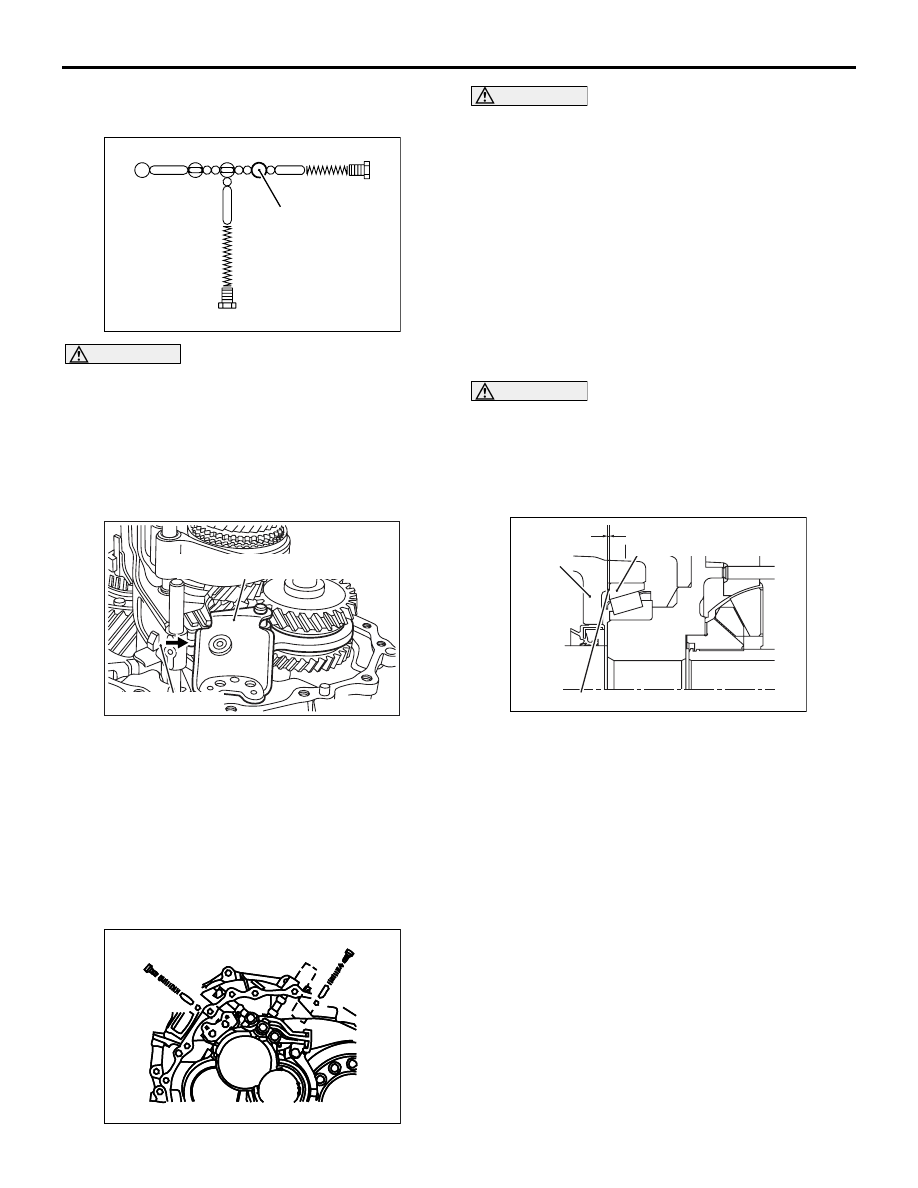
>>H<< REVERSE BRACKET FORK ROD / 
REVERSE BRACKET INSTALLATION

AK204453AC

Reverse shift check parts

Reverse bracket
fork rod

CAUTION

Install the reverse bracket fork rod with its two 
grooves facing the reverse shift check parts.
Install the reverse bracket fork rod and reverse 
bracket.

>>I<< REVERSE LEVER ASSEMBLY 
INSTALLATION

AK203322AD

Reverse lever assembly

Reverse bracket

1. Install the shifter cap on the cam of the reverse 

lever assembly, and then install the reverse shift 
fork.

2. Raise the reverse shift fork and fit its cam in the 

reverse bracket.

>>J<< SHIFT CHECK SLEEVE / CHECK 
BALL / CHECK SPRING / CHECK BALL 
PLUG INSTALLATION

AK204381

AK204381AC

B

A

CAUTION

• The check balls are not reusable.
• Confirm the lengths of the shift check sleeves 

and check springs before installing them. (A: 
short, B: long)

• Be careful not to let the check balls drop into 

the air breathing grooves in the clutch hous-
ing.

Install the two shift check sleeves, two check balls, 
two check springs and two check ball plugs into posi-
tion.

>>K<< DIFFERENTIAL SIDE BEARING 
ADJUSTMENT SHIM INSTALLATION

CAUTION

Do not use more than two shims.
Install the appropriate adjustment shims that will pro-
vide the differential side bearing with a preload within 
the standard value range.

Standard value: 0.15 

 0.21 mm

AK204383AC

L

Transmission
case

Differential side bearing
outer race

Adjustment shim

1. Selecting appropriate shims

(1) Measure the distance between the end 

surface and the adjustment shim fitting surface 
on the transmission case (L1). Next, measure 
the distance between the clutch housing end 
surface and the differential side bearing end 
surface (L2).

(2) Use the following equation to calculate the 

clearance L between the transmission case 
and the differential side bearing outer race:

L = L1 

 L2

(3) Select an adjustment shim (or a set of 

adjustment shims) with a thickness of L plus 
0.15 mm to 0.21 mm (standard value range).

AK204355AC

MB991969

L1

MB991969

Straight edge

Straight edge

Measurement “a”

TRANSMISSION

MANUAL TRANSMISSION OVERHAUL

22B-18

2. Measuring distances L1 and L2

(1) Install the special tool Adjustment adapter 

(MB991969) into the differential side rear 
bearing hole in the transmission case. Use the 
following equation to calculate the distance L1 
(see the illustration above):

L1 = 25.00 (height of MB991969) 

 measure-

ment "a"

(2) Attach the outer race onto the differential side 

bearing on the final gear side, and rotate the 
final gear set five or more times by hand while 
holding the outer race down lightly to keep it 
from tilting.

NOTE: Rotating the final gear in this way will 
help the bearing rollers to seat completely 
against their races.

AK204382AC

Pick tester

Height gauge

CAUTION

Before making the following measurement, make 
sure to confirm that the outer race is level by 
measuring the height of the outer race surface at 
three different points.

(3) Use a height gauge to measure the distance 

between the differential side bearing outer 
race and the transmission mounting surface of 
the clutch housing (L2).

>>L<< DIFFERENTIAL SIDE BEARING 
OUTER RACE INSTALLATION

AK203785

1. Heat the transmission case to about 100

°C 

(maximum temperature: 120

°C).

AK204354

AK204354AC

MB991966

2. Using the special tool Bearing outer race installer 

(MB991966) to install the differential side bearing 
outer race.

TRANSMISSION

MANUAL TRANSMISSION OVERHAUL

22B-19

>>M<< ADJUSTMENT SHIM 
INSTALLATION (INPUT SHAFT REAR 
BEARING / MAIN SHAFT REAR BEARING 
/ REVERSE IDLER GEAR) 

CAUTION

Use only one shim each for the main shaft rear 
bearing, input shaft rear bearing and reverse 
idler gear.
Install the selected shims into the relevant locations.
(Refer to adjustment of transmission - shim selection 
for adjustment of input shaft rear bearing end play, 
main shaft rear bearing end play and reverse idler 
gear end play)

P.22B-23

)

>>N<< TRANSMISSION CASE 
INSTALLATION

CAUTION

The snap ring is not reusable.
1. Install the snap ring temporarily in the main shaft 

rear bearing location in the transmission case.

AK204379

AK204379AC

2. Apply sealant as indicated in the above 

illustration.

Specified sealant: MITSUBISHI GENUINE 
PART MD997740 or equivalent

3. Expand the snap ring in the main shaft rear 

bearing location through the bore plug mounting 
hole and place the transmission case over the 
clutch housing.

AK204378AC

A

A

A

A

A

A

A

A

A

A

B

B

B

B

B

B

B

B

B

A

A

Bolt colors

 A: Yellow
 B: Black

CAUTION

Bolts (B) are not reusable.
4. Tighten all the bolts to the specified torque.

>>O<< CONTROL ASSEMBLY 
INSTALLATION

CAUTION

The O-ring is not reusable.

AK204384

AK204384AC

1

2

1. Install the control assembly and tighten the bolts 

to the specified torque.

2. With the gear shifted into 2nd, raise the main shaft 

and install the snap ring tightly on the main shaft 
rear bearing.
NOTE: 
To shift the gear into 2nd, move the lever in the 
order of the numbers indicated in the illustration.

>>P<< REVERSE SWITCH INSTALLATION

1. Apply sealant to the threads on the reverse 

switch.

Specified sealant: MITSUBISHI GENUINE 
PART MD997740 or equivalent

2. Install the reverse switch on the transmission 

case.

TRANSMISSION

MANUAL TRANSMISSION OVERHAUL

22B-20

ADJUSTMENT OF TRANSMISSION

M1222013800011

SHIM SELECTION FOR ADJUSTMENT OF 
INPUT SHAFT REAR BEARING END 
PLAY, MAIN SHAFT REAR BEARING END 
PLAY AND REVERSE IDLER GEAR END 
PLAY
<Measurement using Solder>

CAUTION

• If solder is not available, select the thrust 

washer in accordance with Plastigage 
method.

• If the thrust washer appropriate for the stand-

ard value cannot be selected using solder, 
select the thrust washer in accordance with 
Plastigage method.

AK204380AC

Solder

1. Put the solder (1.0 mm diameter, about 10 mm 

long) on the input shaft rear bearing as indicated 
in the illustration.

AK204385AC

Solder

2. Put the solder (1.0 mm diameter, about 10 mm 

long) on the main shaft rear bearing fitting surface 
in the transmission case as indicated in the 
illustration.

AK204386AC

Solder

3. In the case of the reverse idler gear: 

(1) Put the solder (1.0 mm diameter, about 10 mm 

long) on the surface of the reverse idler gear 
mounting boss in the transmission case as 
indicated in the Illustration.

(2) Install the adjusting shim having minimum 

thickness.

4. Install the snap ring temporarily in the main shaft 

rear bearing location in the transmission case. 

5. Expand the snap ring in the main shaft rear 

bearing location through the bore plug mounting 
hole, and place the transmission case over the 
clutch housing.

AK204378AC

A

A

A

A

A

A

A

A

A

A

B

B

B

B

B

B

B

B

B

A

A

Bolt colors

 A: Yellow
 B: Black

CAUTION

In the following step, use the same transmission 
case bolts that were removed during disassem-
bly.
6. Install and tighten the transmission case bolts to 

the specified torque.

AK204384

AK204384AC

1

2


Content   ..  291  292  293  294   ..