Mitsubishi Lancer Evolution IX. Manual - part 296
 

  Index      Mitsubishi     Mitsubishi Lancer Evolution IX - service repair manual


Search            


Content   ..  294  295  296  297   ..


Mitsubishi Lancer Evolution IX. Manual - part 296


INPUT SHAFT

MANUAL TRANSMISSION OVERHAUL

22B-29

INSPECTION

M1222001700147

INPUT SHAFT

AK204168

AK204168AC

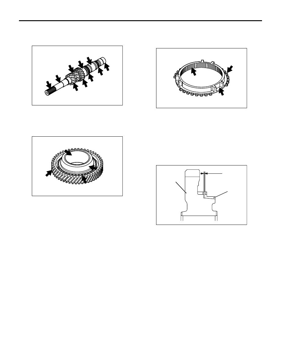
Check the input shaft for damage, flaking, dents, 
uneven wear, bend, and other defects.

SPEED GEARS

AK204169

AK204169AC

1. Check the helical gear teeth and clutch gear teeth 

of each speed gear for damage and excessive 
wear.

2. Check the synchronizer cone surface of each 

speed gear for roughness, damage, and 
excessive wear (3rd gear excepted).

3. Check the inside surface and front and back sides 

of each speed gear for damage and excessive 
wear.

NEEDLE ROLLER BEARINGS

1. Combine each needle roller bearing with the input 

shaft, corresponding sleeve, and gear. Rotate the 
assembly, checking for smooth rotation, 
looseness, and noise.

2. Check the retainer for deformation.

SINGLE CONE SYNCHRONIZER RING

AK204170

AK204170AC

1. Check the clutch gear on the synchronizer ring for 

damaged and missing teeth.

2. Check the synchronizer ring inner cone surface 

for damage or wear. Also check that the inside 
ridges are intact.

3. Check the synchronizer key contact surfaces of 

the synchronizer ring for damage, and excessive 
wear.

AK204104

A

AE

Speed gear

Synchronizer ring

4. Press the synchronizer ring against the cone of 

the adjacent speed gear, and check clearance A. 
Replace the synchronizer ring if the clearance is 
below the limit.

Limit: 0.7 mm

INPUT SHAFT

MANUAL TRANSMISSION OVERHAUL

22B-30

DOUBLE CONE SYNCHRONIZER RING

AK204172AC

Inner synchronizer ring

Synchronizer ring
cone

Outer synchronizer ring

1. Check the clutch gear on the outer synchronizer 

ring for damaged and missing teeth.

2. Check the contact surfaces between each 

synchronizer ring and synchronizer cone for 
damage and wear. Also check that the cone 
ridges are intact.

3. Check the synchronizer key contact surfaces of 

the outer synchronizer ring for damage and 
excessive wear.

AK204173 AC

A

B

Inner synchronizer ring

Synchronizer ring cone

Outer synchronizer ring

4. Combine the synchronizer rings and synchronizer 

cone, and check clearances A and B shown in the 
illustration. Replace them if either of the 
clearances is greater than the limit.

Limit: 0.2 mm

SYNCHRONIZER KEYS

AK204174

AK204174AC

Check the synchronizer hub contact surfaces of each 
synchronizer key for damage and excessive wear.

SYNCHRONIZER SPRINGS

Check the synchronizer springs for loss of tension, 
deformation, and breakage.

REVERSE IDLER GEAR

MANUAL TRANSMISSION OVERHAUL

22B-31

REVERSE IDLER GEAR

DISASSEMBLY AND REASSEMBLY

M1222012500125

AK204079

AK204079

4

5

6

2

3

7

8

9

11

13

14

10

AC

1

12

Apply gear oil to
all moving parts
before installation.

Disassembly steps 

1. Rear reverse idler gear assembly
2. Rear reverse idler gear

<<A>> >>B<<

3. Reverse idler gear sleeve

>>A<<

4. Insert spring
5. Synchronizer ring
6. Needle bearing
7. Washer
8. Thrust bearing

9. Front reverse idler gear
10. Needle bearing
11. Washer
12. Thrust bearing
13. Pin
14. Reverse idler fear shaft

Disassembly steps (Continued)

REVERSE IDLER GEAR

MANUAL TRANSMISSION OVERHAUL

22B-32

DISASSEMBLY SERVICE POINTS
<<A>> REVERSE IDLER GEAR SLEEVE 
REMOVAL

AK204113AC

Match marks

CAUTION

Meshing problems may occur if the original 
spline engagement phase is changed during 
reassembly. 
Make match marks on the reverse idler gear sleeve 
and reverse idler gear hub.

REASSEMBLY SERVICE POINTS
>>A<< INSERT SPRING INSTALLATION

AK204114AC

Clutch 
housing 
side

Install each insert spring on the reverse idler gear 
sleeve, making sure to insert it in the right direction.

>>B<< REVERSE IDLER GEAR SLEEVE 
INSTALLATION

AK204113AC

Match marks

CAUTION

Meshing problems may occur if the spline 
engagement phase is changed during reassem-
bly.
Align the match marks when engaging the splines.

INSPECTION

M1222012400043

REVERSE IDLER SHAFT

AK204101

AK204101AC

Check the reverse idler shaft for damage, flaking, 
dents, uneven wear, bend, and other defects.

THRUST BEARING

1. Check the thrust bearing for smooth rotation, 

without looseness or noise, when rotated together 
with the washers.

2. Check the retainer for deformation.

NEEDLE BEARING

1. Check the needle bearing for smooth rotation, 

without looseness or noise, when rotated together 
with the reverse idler gear and shaft.

2. Check the retainer for deformation.

FRONT REVERSE IDLER GEAR

AK204102

AK204102AC

1. Check the helical gear teeth and clutch gear teeth 

of the reverse idler gear for damage and 
excessive wear.


Content   ..  294  295  296  297   ..