Mitsubishi Lancer Evolution IX. Manual - part 278
 

  Index      Mitsubishi     Mitsubishi Lancer Evolution IX - service repair manual


Search            


Content   ..  276  277  278  279   ..


Mitsubishi Lancer Evolution IX. Manual - part 278


COMBINATION METER ASSEMBLY

CHASSIS ELECTRICAL

54A-49

DIAGNOSIS PROCEDURE 

STEP 1. Check combination meter connector 
C-01 for loose, corroded or damaged terminals, 
or terminals pushed back in the connector.

AC310446

Connector: C-01 
<L.H. drive vehicles>

Harness side

BF

AC310456

Connector: C-01 
<R.H. drive vehicles>

Harness side

AU

Q: Is combination meter connector C-01 in good 

condition?
YES : 

Go to Step 2.

NO : 

Repair or replace the damaged 
component(s). If the functions, which are 
described in "CIRCUIT OPERATION", work 
normally, the input signal from the ignition 
switch (IG1) should be normal.

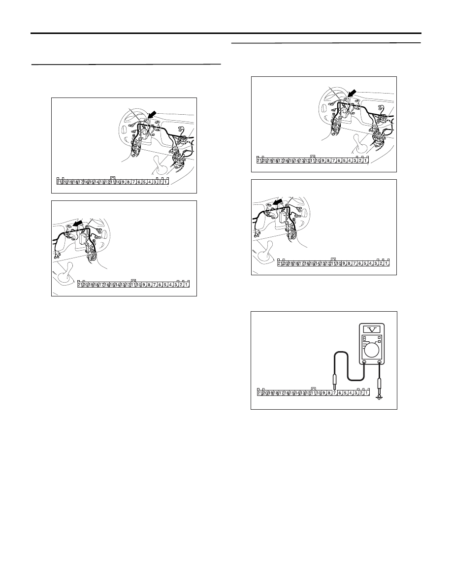
STEP 2. Check the battery power supply circuit 
to the combination meter. Voltage measurement 
at combination meter connector C-01.

AC310446

Connector: C-01 
<L.H. drive vehicles>

Harness side

BF

AC310456

Connector: C-01 
<R.H. drive vehicles>

Harness side

AU

(1) Disconnect combination meter connector C-01 

and measure the voltage available at the wiring 
harness side of the connector.

AC301541

Connector C-01 
(Harness side)

HT

(2) Measure the voltage between terminal 7 and 

earth.

OK: System voltage

Q: IS the check result normal?

YES : 

Go to Step 4.

NO : 

Go to Step 3.

COMBINATION METER ASSEMBLY

CHASSIS ELECTRICAL

54A-50

STEP 3. Check the wiring harness between 
combination meter connector C-01 (terminal 7) 
and battery.

AC310447

Connectors: C-01, C-05, C-129
<L.H. drive vehicles>

AX

C-01

C-01

C-129

C-05(GR)

C-05

C-129

Harness side

AC310456

Connector: C-01 
<R.H. drive vehicles>

Harness side

AU

AC310455

Connectors: C-05, C-129
<R.H. drive vehicles>

AL

C-129

C-05(GR)

C-05

C-129

NOTE: Also check intermediate connector C-129 
and joint connector C-05 for loose, corroded, or dam-
aged terminals, or terminals pushed back in the con-
nector. If intermediate connector C-129 or joint 
connector C-05 is damaged, repair or replace the 
connector.

Q: Is the wiring harness between combination meter 

connector C-01 (terminal 7) and battery in good 
condition?
YES : 

There is no action to be taken.

NO : 

Repair the wiring harness. Check to see that 
all meters operate.

COMBINATION METER ASSEMBLY

CHASSIS ELECTRICAL

54A-51

STEP 4. Check the ignition switch (IG1) circuit to 
the combination meter. Voltage measurement at 
combination meter connector C-01.

AC310446

Connector: C-01 
<L.H. drive vehicles>

Harness side

BF

AC310456

Connector: C-01 
<R.H. drive vehicles>

Harness side

AU

(1) Disconnect combination meter connector C-01 

and measure the voltage available at the wiring 
harness side of the connector.

(2) Turn the ignition switch to the "ON" position.

AC301541

Connector C-01 
(Harness side)

HT

(3) Measure the voltage between terminal 9 and 

earth.

OK: System voltage

Q: Is the check result normal?

YES : 

Go to Step 6.

NO : 

Go to Step 5.

STEP 5. Check the wiring harness between 
combination meter connector C-01 (terminal 9) 
and ignition switch (IG1).

AC310447

C-23(B)

C-01

AY

C-23

Connectors: C-01, C-23
<L.H. drive vehicles>

C-01

Harness side

AC310456

Connector: C-01 
<R.H. drive vehicles>

Harness side

AU

COMBINATION METER ASSEMBLY

CHASSIS ELECTRICAL

54A-52

NOTE: 

AC310449

Junction block
 (Front view)

Connectors: C-211, C-214 
<L.H. drive vehicles>

C-211

C-214

Harness side

AR

C-211

C-214

AC310459

Junction block
 (Front view)

Connectors: C-211, C-214 
<R.H. drive vehicles>

C-211

C-214

Harness side

AR

C-211

C-214

Also check junction block connector C-211 and 
C-214, joint connector C-23 <LH drive vehicles> for 
loose, corroded, or damaged terminals, or terminals 
pushed back in the connector. If junction block con-
nector C-211 or C-214 or joint connector C-23 <LH 
drive vehicles> is damaged, repair or replace the 
connector.

Q: Is the wiring harness between combination meter 

connector C-01 (terminal 9) and ignition switch 
(IG1) in good condition?
YES : 

There is no action to be taken.

NO : 

Repair the wiring harness. Check to see that 
all meters operate.

STEP 6. Check the earth circuit to the 
combination meter. Resistance measurement at 
combination meter connector C-01.

AC310446

Connector: C-01 
<L.H. drive vehicles>

Harness side

BF

AC310456

Connector: C-01 
<R.H. drive vehicles>

Harness side

AU

(1) Disconnect combination meter connector C-01 

and measure the resistance available at the 
wiring harness side of the connector.

AC301541HV

Connector: C-01 
(Harness side)

(2) Measure the resistance between terminal 1 and 

earth.

OK: 2 ohms or less


Content   ..  276  277  278  279   ..