Mitsubishi Lancer Evolution IX. Manual - part 276
 

  Index      Mitsubishi     Mitsubishi Lancer Evolution IX - service repair manual


Search            


Content   ..  274  275  276  277   ..


Mitsubishi Lancer Evolution IX. Manual - part 276


COMBINATION METER ASSEMBLY

CHASSIS ELECTRICAL

54A-41

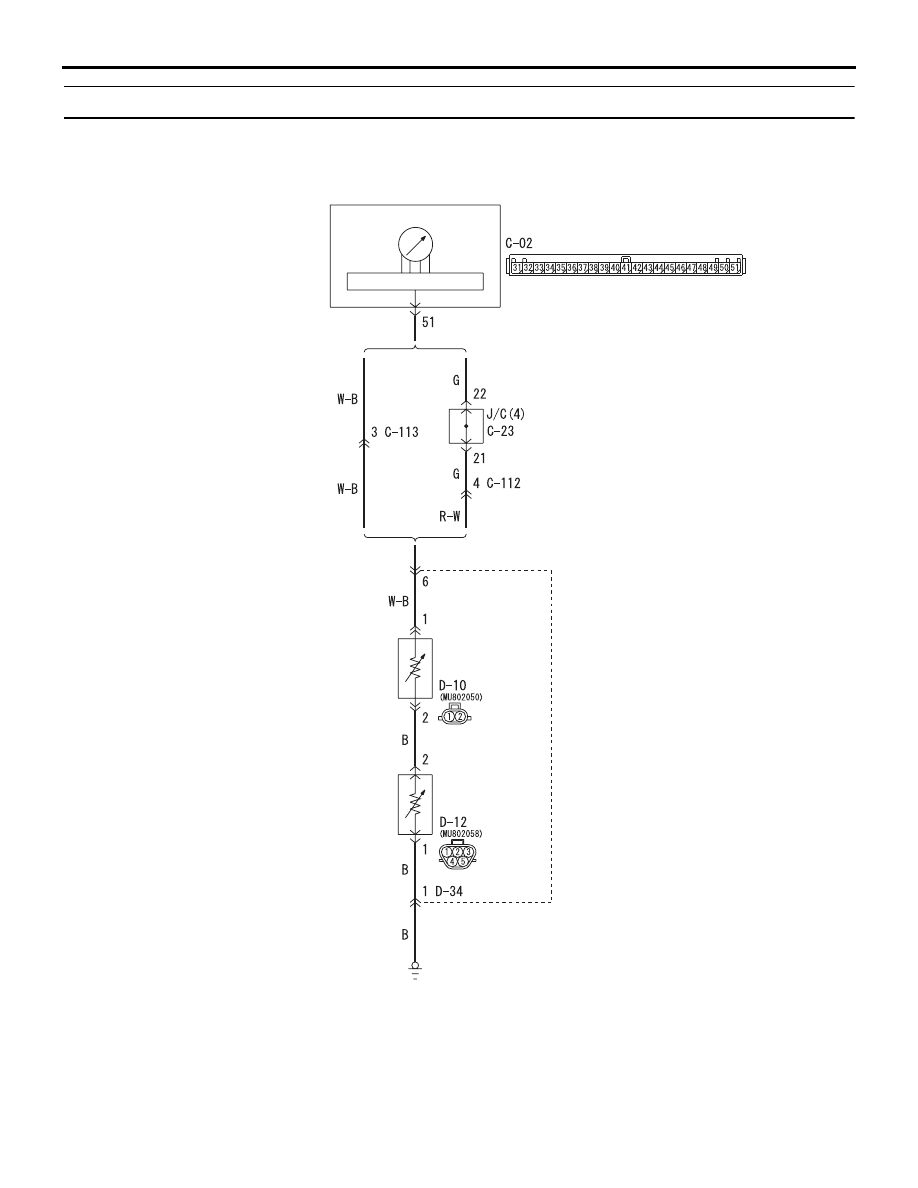
INSPECTION PROCEDURE 3: Fuel gauge does not work.

AC504369AB

Fuel Gauge Circuit

COMBINATION
METER

CONTROL CIRCUIT

F/GA

R.H. drive vehicles

L.H. drive vehicles

FUEL
GAUGE
UNIT (SUB)

FUEL PUMP
AND GAUGE
UNIT (MAIN)

Wire colour code
B : Black     LG : Light green     G : Green     L : Blue     W : White     Y : Yellow     SB : Sky blue
BR : Brown     O : Orange     GR : Gray     R : Red     P : Pink     V : Violet

TECHNICAL DESCRIPTION (COMMENT)

If only the fuel gauge does not operate, fuel gauge 
unit the combination meter, wiring harness or con-
nector(s) may be defective.

COMBINATION METER ASSEMBLY

CHASSIS ELECTRICAL

54A-42

TROUBLESHOOTING HINTS

• Malfunction of the fuel gauge unit.

• The wiring harness or connectors may have 

loose, corroded, or damaged terminals, or termi-
nals pushed back in the connector.

• Malfunction of the combination meter.

DIAGNOSIS PROCEDURE 

STEP 1. Check the other meters.

Check to see that the speedometer, fuel gauge 
and water thermometer operate normally.

Q: Do all other meters operate?

Yes <other meters all operate> : 

Go to Step 2.

NO <one or more of the other meters does not 
operate.>  : 

Refer to 

P.54A-48

.

STEP 2. Check fuel gauge unit (sub) connector 
D-10 and fuel gauge umit (main) connector D-12 
for loose, corroded or damaged terminals, or 
terminals pushed back in the connector.

AC310465

AK

D-10

D-10

D-12(GR)

Harness side

D-12
Harness side

Connectors: D-10, D-12

Q: Are fuel gauge unit (sub) connector D-10 and fuel 

gauge unit (main) connector D-12 in good 
condition?
YES : 

Go to Step 3.

NO : 

Repair or replace the damage 
component(s). The fuel gauge should work 
normally.

STEP 3. Check the fuel gauge unit (sub) and fuel 
gauge unit (main).

Check to see that the fuel gauge unit (sub) and 
fuel gauge unit (main) are normal. Refer to 

P.54A-54

.

Q: Are fuel gauge unit (sub) and fuel gauge unit 

(main) normal?
Yes  : 

Go to Step 4.

NO  : 

Replace fuel gauge unit (sub) and fuel 
gauge unit (main). The fuel gauge should 
work normally.

STEP 4. Check the earth circuit to the fuel gauge 
unit (main). Resistance measurement at fuel 
gauge unit (main) connector D-12.

AC310465

AL

D-12(GR)

Harness side

Connector: D-12

(1) Disconnect fuel gauge unit (main) connector 

D-12 and measure the resistance available at the 
wiring harness side of the connector.

2

3

5

1

4

AC211567

Connector D-12
(Harness side)

AC

(2) Measure the resistance value between terminal 1 

and earth.

OK: 2 ohms or less

Q: Is the check result normal?

YES : 

Go to Step 6.

NO : 

Go to Step 5.

COMBINATION METER ASSEMBLY

CHASSIS ELECTRICAL

54A-43

STEP 5. Check the wiring harness between fuel 
gauge unit (main) connector D-12 (terminal 1) 
and earth.

AC310465

AL

D-12(GR)

Harness side

Connector: D-12

NOTE: 

AC310463

AH

Harness side

Connector: D-34

Also check intermediate connector D-34 for loose, 
corroded, or damaged terminals, or terminals pushed 
back in the connector. If intermediate connector D-34 
is damaged, repair or replace the connector.

Q: Is the wiring harness between fuel gauge unit 

(main) connector D-12 (terminal 1) and earth in 
good condition?
YES : 

There is no action to be taken.

NO : 

Repair the wiring harness. The fuel gauge 
should work normally.

STEP 6. Check combination meter connector 
C-02 for loose, corroded or damaged terminals, 
or terminals pushed back in the connector.

AC310446

Connector : C-02
<L.H. drive vehicles> 

Harness side

BG

C-02(L)

AC310456

Connector : C-02
<R.H. drive vehicles> 

Harness side

AV

C-02(L)

Q: Is combination meter connector C-02 in good 

condition?
YES : 

Go to Step 7.

NO : 

Repair or replace the damaged 
component(s). The fuel gauge should work 
normally.

COMBINATION METER ASSEMBLY

CHASSIS ELECTRICAL

54A-44

STEP 7. Check the wiring harness between fuel 
gauge unit (sub) connector D-10 (terminal 1) and 
combination meter connector C-02 (terminal 51).

AC310465

AM

Harness side

Connector: D-10

AC310446

Connector : C-02
<L.H. drive vehicles> 

Harness side

BG

C-02(L)

AC310456

Connector : C-02
<R.H. drive vehicles> 

Harness side

AV

C-02(L)

NOTE: 

AC310452

CONNECTOR: C-113
<L.H. drive vehicles> 

AZ

AC310457

AC310457

Connectors: C-23, C-112
<R.H. drive vehicles>

C-112(GR)

C-23(B)

C-23

C-112

AH

AC310463

AH

Harness side

Connector: D-34

Also check intermediate connectors C-112 <RH drive 
vehicles>, C-113 <LH drive vehicles>, D-34 and joint 
connector C-23 <RH drive vehicles> for loose, cor-
roded, or damaged terminals, or terminals pushed 
back in the connector. If intermediate connector 
C-112 <RH drive vehicles>, C-113 <LH drive vehi-
cles> or D-34 and joint connector C-23 <RH drive 
vehicles> is damaged, repair or replace the connec-
tor.


Content   ..  274  275  276  277   ..