Mitsubishi Lancer Evolution IX. Manual - part 279
 

  Index      Mitsubishi     Mitsubishi Lancer Evolution IX - service repair manual


Search            


Content   ..  277  278  279  280   ..


Mitsubishi Lancer Evolution IX. Manual - part 279


COMBINATION METER ASSEMBLY

CHASSIS ELECTRICAL

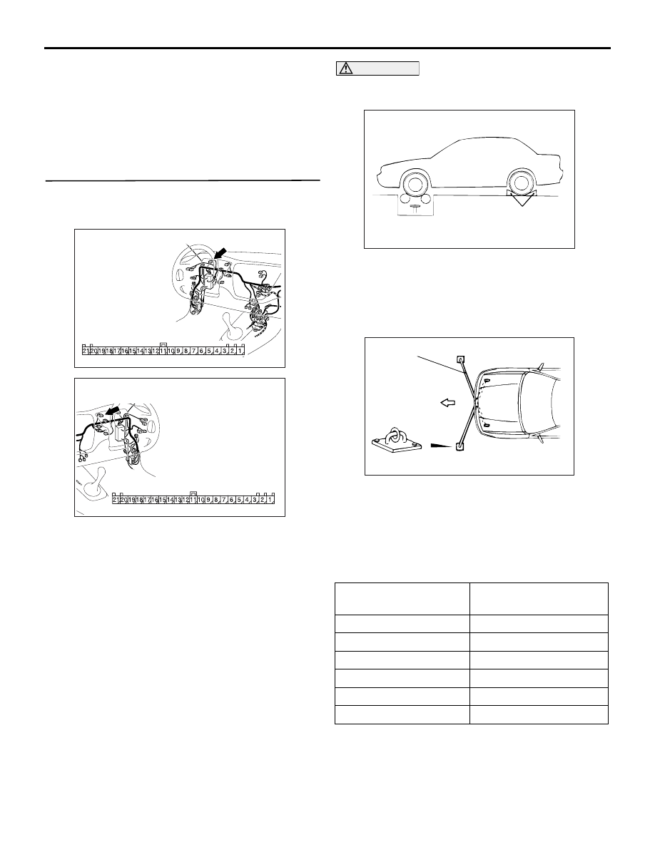
54A-53

(3) Measure the resistance between terminal 2 and 

earth.

OK: 2 ohms or less

Q: Is the check result normal?

YES : 

Repair or replace the combination meter. 

Check to see that all meters operate.

NO : 

Go to Step 7.

STEP 7. Check the wiring harness between 
combination meter connector C-01 (terminals 1 
and 2) and earth.

AC310446

Connector: C-01 
<L.H. drive vehicles>

Harness side

BF

AC310456

Connector: C-01 
<R.H. drive vehicles>

Harness side

AU

Q: Are the wiring harness between combination meter 

connector C-01 (terminals 1 and 2) and earth in 
good condition?
YES : 

There is no action to be taken.

NO : 

Repair the wiring harness. Check to see that 
all meters operate.

ON-VEHICLE SERVICE

SPEEDOMETER CHECK

M1543000900531

1. Adjust the pressure of tyres to the specified level. 

(Refer to GROUP 31, On-vehicle Service 

P.31-7

).

CAUTION

Do not operate the clutch suddenly. Do not 
increase/decrease speed rapidly while testing.

AC305135AB

Wheel stopper

2. Set the vehicle onto a speedometer tester and 

use wheel chocks to hold the rear wheels.

3. To prevent the front wheel from moving from side 

to side, attach tension bars to the tie-down hook, 
and secure both ends to anchor plates.

AC001288

Tension bar

Front

Anchor plate

AB

4. To prevent the vehicle from moving, attach a chain 

or wire to the rear retraction hook, and make sure 
the end of the chain or wire is secured.

5. Check if the speedometer indicator range is within 

the standard values.

Standard value:

Standard indicator 
km/h

Allowance range km/h

20

20 

− 24

40

40 

− 44

80

80 

− 85

120

121 

− 127

160 

162 

− 169

200

203 

− 211

6. If not to the standard value, inspect for proper tyre 

size. If not correct, replace the tyres with original 
size tyres and retest. If correct, replace the 
speedometer. If still not to standard value, replace 
the vehicle speed sensor.

COMBINATION METER ASSEMBLY

CHASSIS ELECTRICAL

54A-54

TACHOMETER CHECK

M1543001000519

AC305138AB

Engine speed 
indicator

Paper clip

Probe for detection
of engine speed

1. Attach an external high quality tachometer to the 

engine speed detection connector on the harness 
side (such as with a paper clip).
NOTE: For tachometer check, use an external 
high quality inductive tachometer.

2. Compare the readings of the vehicle tachometer 

and the external tachometer at every engine 
speed, and check if the variations are within the 
standard values.

Standard values:

Engine speed (r/min)

Indication allowance 
of tachometer r/min

700

± 120

2, 000

− 175 + 225

3, 000

− 175 + 300

4, 000

− 225 + 375

5, 000

− 225 + 425

6, 000

− 225 + 475

7, 000

− 200 + 500

8, 000

− 100 + 500

FUEL TANK GAUGE UNIT CHECK

M1543001200643

Remove the fuel tank gauge unit (Refer to GROUP 
13B, Fuel Tank 

P.13B-5

).

FUEL TANK GAUGE UNIT RESISTANCE
Fuel gauge unit (main)

AC211789

2

1

4

3

5

Fuel gauge unit

AD

Earth

Position F

Position E

1. Check that resistance value between the fuel 

gauge terminal and earth terminal is at the 
standard value when the fuel tank gauge unit float 
is between position "F" (highest) and position "E" 
(lowest).

Standard values:

Float Position

Resistance of Gauge

Position F

± 1 Ω

Position E

36.4 

± 1 Ω

2. Check that resistance value changes smoothly 

when the float moves slowly between position "F" 
(highest) and position "E" (lowest). 

3. If all checks are correct, go to fuel tank gauge unit 

float height check. If any check is not correct, 
replace the fuel tank gauge unit.

COMBINATION METER ASSEMBLY

CHASSIS ELECTRICAL

54A-55

Fuel gauge unit (sub)

;

AC310332

Fuel gauge unit

AB

Earth

Position F

Position E

1. Check that resistance value between the fuel 

gauge terminal and earth terminal is at the 
standard value when the fuel tank gauge unit float 
is between position "F" (highest) and position "E" 
(lowest).

Standard values:

Float Position

Resistance of Gauge

Position F

± 1 Ω

Position E

73.6 

± 1 Ω

2. Check that resistance value changes smoothly 

when the float moves slowly between position "F" 
(highest) and position "E" (lowest). 

3. If all checks are correct, go to fuel tank gauge unit 

float height check. If any check is not correct, 
replace the fuel tank gauge unit.

FUEL TANK GAUGE UNIT FLOAT HEIGHT
Fuel gauge unit (main)

AC211788AC

A

Position F

Position E

B

Stopper

1. Move the float and measure height A at position 

"F" (highest) and B at position "E" (lowest) with 
the float arm touching stopper.

Standard values:

Float Position

Float Centre Height

Position F (A)

33.3 

± 2.0 mm

Position E (B)

121.9 

± 2.0 mm

2. If all checks are correct, go to fuel tank gauge unit 

float height check. If any check is not correct, 
replace the fuel tank gauge unit.

Fuel gauge unit (sub)

AC211590AD

A

Position F

Position E

B

Stopper

1. Move the float and measure height A at position 

"F" (highest) and B at position "E" (lowest) with 
the float arm touching stopper.

Standard values:

Float Position

Float Centre Height

Position F (A)

5.7 

± 2.0 mm

Position E (B)

141.0 

± 2.0 mm

2. If all checks are correct, go to fuel tank gauge unit 

float height check. If any check is not correct, 
replace the fuel tank gauge unit.

COMBINATION METER ASSEMBLY

CHASSIS ELECTRICAL

54A-56

ENGINE COOLANT TEMPERATURE 
GAUGE UNIT CHECK

M1543001500484

1. Drain the engine coolant (Refer to GROUP 14, 

On-vehicle Service 

P.14-15

).

2. Remove the engine coolant temperature gauge 

unit.

ACX00779 AI

Circuit tester

Thermometer

3. Put engine coolant temperature gauge unit into 

the hot water in specified temperature, and 
ensure that basic resistance is within standard 
value.

Standard value: 104 

± 13.5  (at 70°C)

Reference value

Temperature 

°C

Resistance 

50 

230

60 

155

80 

73

ACX00780AH

11 ± 1 N·m

4. After inspection, apply specified sealant at 

threads of engine coolant temperature gauge unit, 
and tighten to the specified torque.

Semi-drying sealant: 3M 1215 or equivalent

5. Add engine coolant (Refer to GROUP 14, 

On-vehicle Service 

P.14-15

).

COMBINATION METER ASSEMBLY

REMOVAL AND INSTALLATION

M1543021300051

AC310333

4

3

2

AB

1

1. Vehicle speed sensor

Removal steps 

2. Meter bezel
3. Instrument panel ornament
4. Combination meter assembly


Content   ..  277  278  279  280   ..