Mitsubishi Eclipse. Technical Information Manual (1994) - part 14
 

  Index      Mitsubishi     Mitsubishi Eclipse. Technical Information Manual (1994)


Search            


Content   ..  12  13  14  15   ..


Mitsubishi Eclipse. Technical Information Manual (1994) - part 14


ENGINE <NON-TURBO>   Control System

Test condition

There are a large number of tests waiting to be
performed once the vehicle is stat-ted. It is the diag-
nostic system’s job to see that these tests are not
only performed, but performed under the appropriate
conditions.

An additional job of the diagnostic system is to pre-
vent false 

 from being stored. The diagnostic

system accomplishes this by not running certain
tests when it recognizes that faults already in the
system or tests currently being run could cause

the next test to fail erroneously. For example:

The test for the catalyst monitor does not run

if the MIL light is on due to an oxygen sensor

fault. The oxygen sensor is a key component

in the catalyst monitor test. If the sensor is not

functioning properly, there is no reason to run
the catalyst monitor 

it won’t pass. This test

will not be run pending repair of the sensor
concern.

The diagnostic system does not run the test

monitoring catalyst operation if the EGR monitor 

test is being run. The EGR monitor is an “intru-
sive” test and will cause the catalyst monitor
to produce data not representative of normal
operating conditions. This represents a conflict
of test data. The diagnostic system will wait

until the EGR monitor is finished before running

the catalyst monitor.

Finally, the results from the catalyst monitor

are always held until the oxygen sensor test
has been successfully completed. The results

from the test are suspended until the required
prerequisite test has been completed.

By reviewing these guidelines, the diagnostic system

avoids storing 

 that are the result of failure

of other components in the system. The diagnostic
system allows you to use the diagnostic scan tool
more confidently in diagnosing and repairing a con-
cern.

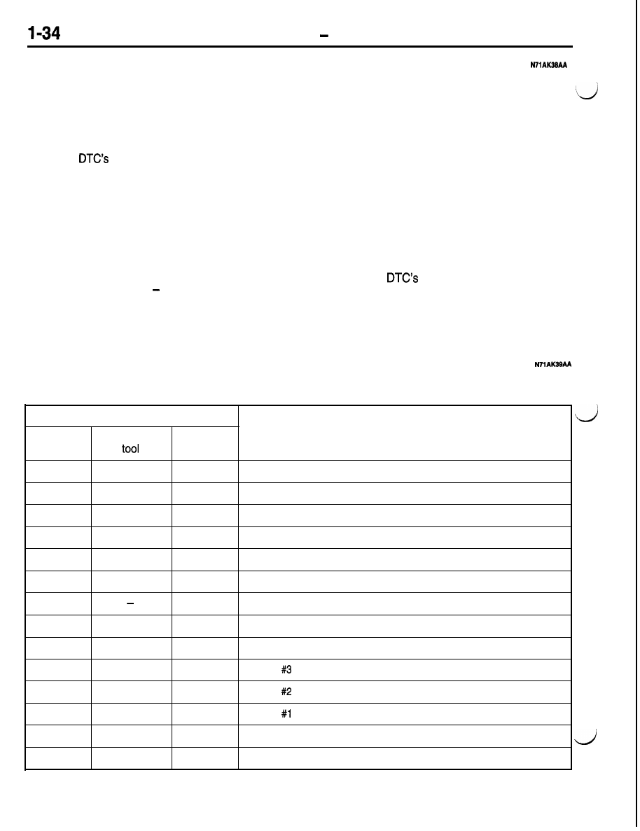
DIAGNOSTIC TROUBLE CODES

The diagnostic items are shown in the following table. Note that a fault’s numeric codes are different,
depending on the method of inspection.

Diagnostic trouble code No.

Scan tool

General scan

Diagnostic items

(MUT-II)

MIL

01

PO340

54

No cam signal at PCM

02

PO605

53

Internal controller failure

05

47

Charging system voltage too low

06

46

Charging system voltage too high

10

42

MFI relay (ASD relay) control circuit

11

41

Generator field not switching properly

16

33

A/C clutch relay circuit

17

PO403

32

EGR solenoid circuit

18

PO443

31

EVAP solenoid circuit

19

PO203

27

Injector   control circuit

20

PO202

27

Injector   control circuit

21

PO201

27

Injector   control circuit

25

PO505

25

Idle air control motor circuits

26

PO122

24

Throttle position sensor voltage low

MIL: Check engine/Malfunction indicator lamp

ENGINE <NON-TURBO>   Control System

Diagnostic trouble code No.

Scan tool

General scan

Diagnostic items

(MUT-II)

MIL

27

PO123

24

Throttle position sensor voltage high

30

PO117

22

Engine coolant temperature sensor voltage too low

31

PO118

22

Engine coolant temperature sensor voltage too high

32

PO134

21

Upstream 

 stays at center

33

17

Engine is cold too long

35

PO500

15

No vehicle speed sensor signal

36

PO1 07

14

MAP sensor voltage too low

37

PO1 08

14

MAP sensor voltage too high

39

P1297

13

No change in MAP from start to run

40

PO335

11

No crank reference signal at PCM

42

PO352

43

Ignition coil 

 primary circuit

43

PO351

43

Ignition coil 

 primary circuit

44

42

No MFI relay (ASD relay) output voltage at PCM

46

PO401

32

EGR system failure

48

62

PCM failure SRI mile not stored

49

63

PCM failure EEPROM write denied

51

PO412

36

Pulsed secondary air injection solenoid circuit 

57

PO112

23

Intake air temperature sensor voltage low

58

PO113

23

Intake air temperature sensor voltage high

59

PO325

16

Knock sensor   circuit

61

PO204

27

Injector 

 control circuit

62

PO132

21

Upstream 

 shorted to voltage

68

PO605

53

PCM failure SPI communications

71

44

Battery temperature sensor volts out of limit

92

35

Low speed fan control relay circuit

93

P1489

35

High speed fan control relay circuit

96

P1698

66

No CCD messages from TCM 

101

42

Fuel pump relay control circuit

102

PO133

21

Upstream 

 response 

103

PO135

21

Upstream 

 heater failure 

MIL: Check engine/Malfunction indicator lamp
SRI: Service Reminder Indicator

ENGINE <NON-TURBO>   Control System

Diagnostic trouble code No.

Scan tool

General scan

(MUT-II)

MIL

104

PO1 39

21

105

PO141

21

106

PO300

43

Diagnostic items

Downstream 

 stays at center 

Downstream 

 heater failure 

Multiple cylinder misfire* 

107

PO301

108

PO302

43

Cylinder   misfire* 

43

Cylinder 

 misfire* 

109

I

PO303

I

43

Cylinder 

 misfire* 

110

I

PO304

I

43

Cylinder 

 misfire* 

111

PO41 1

112

PO422

113

PO441

36

Too little secondary air or too much secondary air 

64

Catalytic converter efficiency failure 

31

Evaporative purge flow monitor failure 

114

P1899

37

 Park/Neutral switch 

115

I

PO551

I

65

 Power steering switch failure 

118

I

PO1 72

I

52

 Fuel system rich*

119

PO171

126

PO138

128

PO125

132

PO121

133

51

Fuel system lean*

21

Downstream 

 shorted to voltage 

17

Closed loop temperature not reached 

24

Throttle position sensor voltage does not agree with MAP 

11

Timing belt skipped 1 tooth or more

138

P1294

I

25

 Target idle not reached 


157

I

P1391

I

11

 Intermittent loss of CMP or CKP

I

I

MIL: Check engine/Malfunction indicator lamp

 The diagnostic code is memorized on the first detection of the trouble.

ENGINE 

   Control Svstem

MAIN MONITORS

To meet OBD II requirements, the on-board diagnos-
tic system must monitor the electrical input signals
and the performance of output responses that can

have an effect on vehicle emissions. In addition,

there are several “main monitors” that review the

result of system operations and their effect on emis-
sions. The main monitors are as follows:

Catalyst

Fuel System

Misfire

 Oxygen Sensor

Exhaust Gas Recirculation

Secondary air (air injection)

Oxygen Sensor Monitor

Background

Effective control of exhaust emissions is achieved
by an oxygen feedback system. The most important


Each of the main monitors is listed below with a
brief background explanation and a description of
how the monitor operates. Following these condi-

tions is the diagnostic trouble code (DTC) this moni-
tor produces along with the DTC 

 number

and a number referred to as a SAE J 2012 or 
code. SAE J 2012 codes required by law for use
with generic diagnostic scan tools.

element in this system is the oxygen 

 sensor

mounted in the exhaust manifold.


Content   ..  12  13  14  15   ..