Mercedes-Benz Sprinter / Dodge Sprinter. Manual - part 468


  Index      Mercedes     Mercedes-Benz Sprinter / Dodge Sprinter - service repair manual 2006 year


Search            


Content   ..  466  467  468  469   ..


Mercedes-Benz Sprinter / Dodge Sprinter. Manual - part 468


ASSEMBLY

(1) Mount thrust washer (4) (Fig. 220) with the

collar pointing towards the planet carrier.

(2) Mount the rear gear set (5) on the rear hollow

shaft (6).

(3) Using grease, install lower three Teflon rings

(1) (Fig. 220) in the groove so that the joint stays
together

(4) Put rear hollow shaft/freewheeling clutch F2

(6) with rear gear set (5) onto output shaft.

(5) Install clutch K3 (7).
(6) Mount retaining ring, shim, thrust needle bear-

ing and thrust washer (8 - 11) (Fig. 220).

(7) Using grease, insert the upper two Teflon rings

(1) in the groove so that the joint remains together.

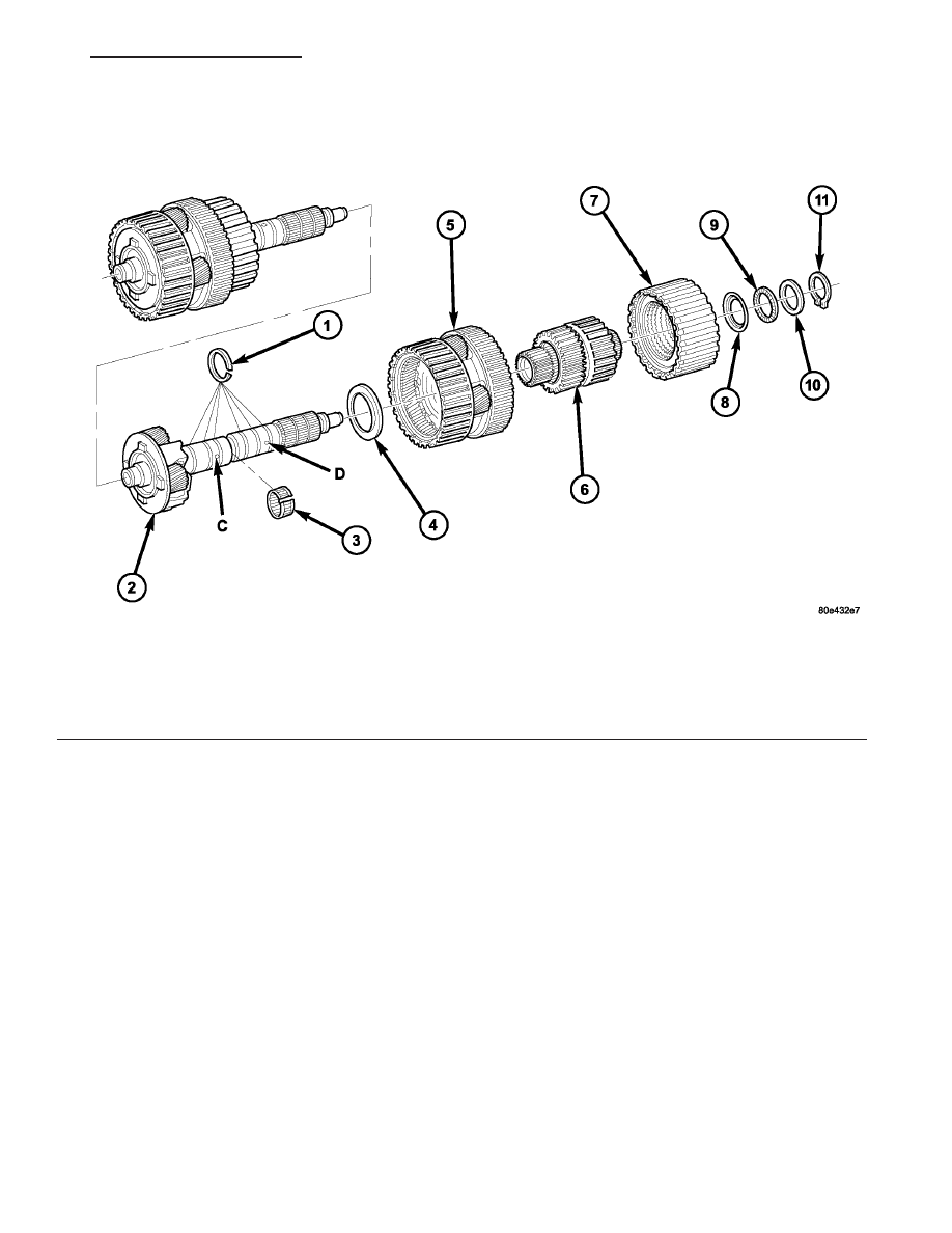
Fig. 220 Output Shaft with Center and Rear Planetary Geartrain

1 - TEFLON RINGS

7 - DRIVING CLUTCH K3

2 - OUTPUT SHAFT WITH CENTER PLANETARY CARRIER

8 - THRUST WASHER

3 - NEEDLE BEARING

9 - AXIAL NEEDLE BEARING

4 - THRUST WASHER

10 - SHIM

5 - REAR PLANETARY GEAR SET

11 - RETAINING RING

6 - REAR HOLLOW SHAFT/FREEWHEELING CLUTCH F2

VA

AUTOMATIC TRANSMISSION NAG1 - SERVICE INFORMATION

21 - 167

NOTE: During the test, apply a contact force by
hand to K3 in the direction of the arrow.

(8) Inspect axial play (Fig. 221) between shim (10)

and retaining ring (11). Check axial play “S” between
shim (10) and retaining ring (1) using a feeler gauge.
Clearance should be 0.15-0.6 mm (0.006-0.024 in.).
Shims are available in thicknesses of 3.0 mm (0.118
in.), 3.4 mm (0.134 in.), and 3.7 mm (0.146 in.).
Adjust as necessary

SHIFT MECHANISM

DESCRIPTION

The automatic transmission is operated with the

help of a shift lever assembly (SLA) located in the
center console. There are four positions to which the
selection lever can be shifted: P, R, N, D. In addition,
the selector lever can be moved sideways (+/-) in posi-
tion “D” to adjust the shift range.

All selector lever positions, as well as selected shift

ranges in position “D”, are identified by the SLA. The
information is then sent to the transmission control
module (TCM) via a hardwire connection. At the
same time, the selector lever positions “P”, “R”, “N”
and “D” are transmitted by a shift cable to the selec-
tor shaft in the transmission.

The SLA is comprised of the following functions:

• Key lock: Depending on the selector lever posi-

tion, the ignition lock is locked/unlocked, i.e., the
ignition key can be removed only if the selector lever
is in position “P”. A park lock cable is used to per-
form this function.

• Park lock: The selector lever is not released

from postion “P” until the brake pedal has been
applied and the ignition key is in driving position.
Shift lock is controlled by the brake light switch in
conjunction with a locking solenoid in the SLA. As
soon as the brake pedal is applied firmly, the locking
solenoid is retracted to unlock the selector lever. If
the selector lever cannot be moved out of position “P”
due to a malfunction, the shift lock function can be
overriden (see operator’s manual).

• Reverse inhibitor: As soon as the vehicle

speed exceeds approx. 4 mph, it is no longer possible
to move the selector lever from position “N” to posi-
tion “R”.

OPERATION

With the selector lever in position “D”, the trans-

mission control module (TCM) automatically shifts
the gears that are best-suited to the current operat-
ing situation. This means that shifting of gears is
continuously adjusted to current driving and operat-
ing conditions in line with the selected shift range
and the accelerator pedal position. Starting off is
always performed in 1st gear.

The selector lever positions are determined by the

slider position of a potentiometer in the shift lever
assembly (SLA). The shift pattern diagram (position
display) and the program selector are illuminated by
the LEDs.

The current selector lever position or, if the shift

range has been limited, the current shift range is
indicated in the LCD display in the instrument clus-
ter.

The permissible shifter positions and transmission

operating ranges are:

• P = Parking lock and engine starting.

• R = Reverse.

• N = Neutral and engine starting (no power is

transmitted to the axles).

• D = The shift range includes all forward gears.

• 4= Shift range is limited to gears 1 to 4.

• 3= Shift range is limited to gears 1 to 3.

• 2= Shift range is limited to gears 1 to 2.

• 1= Shift range is limited to the 1st gear.
The shift range can be adjusted to the current

operating conditions by tipping the selector lever to
the left-hand side (“-”) or the right-hand side (“+”)
when in position “D”. If the shift range is limited, the
display in the instrument cluster indicates the
selected shift range and not the currently engaged
gear.

Tipping the shift lever will have the following

results:

Fig. 221 Check Center and Rear Planetary End-Play

1 - DRIVING CLUTCH K3
2 - THRUST WASHER
3 - SHIM
4 - AXIAL NEEDLE BEARING
5 - RETAINING RING
6 - OUTPUT SHAFT WITH CENTER PLANETARY CARRIER

21 - 168

AUTOMATIC TRANSMISSION NAG1 - SERVICE INFORMATION

VA

• Tipping the selector lever toward “-” one

time after another: The shift range is reduced in
descending sequence by one gear each time, i.e., from
D - 4 - 3 - 2 - 1. If the selected limitation of the shift
range would result in a downshift causing excessive
engine speed, the shifting is not executed and the
engaged gear as well as the shift range remain
unchanged. This is to prevent the engine from over-
speeding. Engine retardation is low with the selector
lever in position “D”. To make use of the full braking
power of the engine, “manual” downshifting by tip-
ping the lever towards the left-hand side is recom-
mended. If this has been done, subsequent upshifting
must be carried out manually as well.

• Tipping the selector lever toward “-” and

holding it in this position: The currently engaged
gear in range “D” is indicated in the instrument clus-
ter display and the shift range is limited to this gear.

• Tipping the selector lever toward “+” one

time after another: The shift range is increased by
one gear each time and the increased shift range is
displayed in the instrument cluster; possibly, the
transmission upshifts to a faster gear.

• Tipping the selector lever toward “+” sev-

eral times: The shift range is increased by one gear
each time the lever is tipped until the shift range
ends up in “D”.

• Tipping the selector lever toward “+” and

holding it in this position: The shift range is
extended immediately to “D”, shift ranges are indi-
cated in ascending sequence; possibly, the transmis-
sion upshifts to a faster gear due to the extension of
the shift range.

REMOVAL

(1) Move selector lever to position “D”.
(2) Remove top section (3) (Fig. 222) of the center

section of instrument panel.

(3) Remove bottom section (2) (Fig. 223) of the cen-

ter section of instrument panel.

Fig. 222 Remove Top Section Of Center Instrument

Panel

1 - SHIFT LEVER ASSEMBLY FRAME TRIM
2 - STORAGE COMPARTMENT
3 - TOP CENTER PART OF INSTRUMENT PANEL
4 - SCREW
5 - PLUG CONNECTIONS
6 - ASHTRAY

Fig. 223 Remove Bottom Section Of Center

Instrument Panel

1 - SCREW
2 - BOTTOM CENTER PART OF INSTRUMENT PANEL

VA

AUTOMATIC TRANSMISSION NAG1 - SERVICE INFORMATION

21 - 169

(4) Disconnect the park lock cable coupling (1)

(Fig. 224) from the shift lever assembly (SLA). Press
locking tab (2) together and push coupling (1) against
the spring force into the SLA, twist through 90°
(right or left) and pull off.

(5) Disconnect connector plug (5) from SLA. When

disconnecting plug, press together at points shown
(arrows).

(6) Pry ball socket (4) of transmission shift cable

off ball knob at the SLA. Use a suitable slotted
screwdriver.

(7) Unscrew bolts (1) (Fig. 225).
(8) Move selector lever to position “P”.
(9) Remove the SLA (2) from the vehicle.

INSTALLATION

(1) Position the shift lever assembly (SLA) onto

the vehicle.

(2) Install the bolts to hold the SLA to the vehicle.

Tighten the bolts to 6 N·m (53 in.lbs.).

(3) Connect the park lock cable coupling (1) (Fig.

226) to the SLA. Press locking tab (2) together and
push coupling (1) against the spring force into the
SLA, twist through 90° (right or left) until locked.

(4) Connect the connector plug (5) to the SLA.

Fig. 224 Disengage Park Lock Cable From SLA

1 - PARK LOCK CABLE COUPLING
2 - LOCK TAB
3 - BOLT
4 - SHIFT LEVER ASSEMBLY (SLA)
5 - CONNECTOR

Fig. 225 Remove SLA

1 - BOLT
2 - SLA
3 - SHIFT CABLE

Fig. 226 Engage Park Lock Cable to SLA

1 - PARK LOCK CABLE COUPLING
2 - LOCK TAB
3 - BOLT
4 - SHIFT LEVER ASSEMBLY (SLA)
5 - CONNECTOR

21 - 170

AUTOMATIC TRANSMISSION NAG1 - SERVICE INFORMATION

VA


Content   ..  466  467  468  469   ..