Mercedes-Benz Sprinter / Dodge Sprinter. Manual - part 467


  Index      Mercedes     Mercedes-Benz Sprinter / Dodge Sprinter - service repair manual 2006 year


Search            


Content   ..  465  466  467  468   ..


Mercedes-Benz Sprinter / Dodge Sprinter. Manual - part 467


(9) Verify repair.

PISTONS

DESCRIPTION

There are several sizes and types of pistons used in

an automatic transmission. Some pistons are used to
apply clutches. They all have in common the fact
that they are round or circular in shape, located
within a smooth walled cylinder, which is closed at
one end and converts fluid pressure into mechanical
movement. The fluid pressure exerted on the piston
is contained within the system through the use of
piston rings or seals.

OPERATION

The principal which makes this operation possible

is known as Pascal’s Law. Pascal’s Law can be stated
as: “Pressure on a confined fluid is transmitted
equally in all directions and acts with equal force on
equal areas.”

PRESSURE

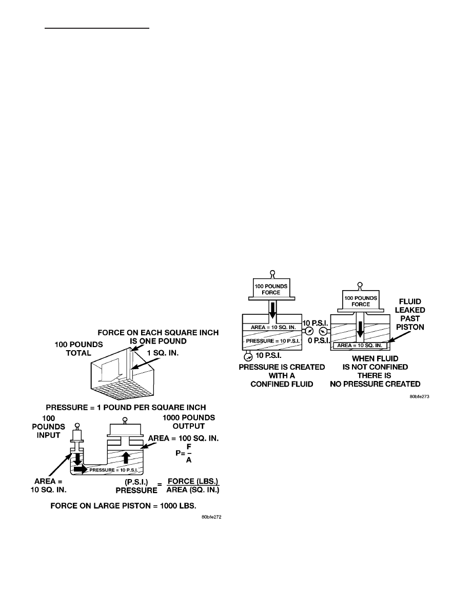
Pressure (Fig. 213) is nothing more than force

(lbs.) divided by area (in or ft.), or force per unit
area. Given a 100 lb. block and an area of 100 sq. in.
on the floor, the pressure exerted by the block is: 100
lbs. 100 in or 1 pound per square inch, or PSI as it is
commonly referred to.

PRESSURE ON A CONFINED FLUID

Pressure is exerted on a confined fluid (Fig. 214)

by applying a force to some given area in contact
with the fluid. A good example of this is a cylinder

filled with fluid and equipped with a piston that is
closely fitted to the cylinder wall. If a force is applied
to the piston, pressure will be developed in the fluid.
Of course, no pressure will be created if the fluid is
not confined. It will simply “leak” past the piston.
There must be a resistance to flow in order to create
pressure. Piston sealing is extremely important in
hydraulic operation. Several kinds of seals are used
to accomplish this within a transmission. These
include but are not limited to O-rings, D-rings, lip
seals, sealing rings, or extremely close tolerances
between the piston and the cylinder wall. The force
exerted is downward (gravity), however, the principle
remains the same no matter which direction is taken.
The pressure created in the fluid is equal to the force
applied, divided by the piston area. If the force is 100
lbs., and the piston area is 10 sq. in., then the pres-
sure created equals 10 PSI. Another interpretation of
Pascal’s Law is that regardless of container shape or
size, the pressure will be maintained throughout, as
long as the fluid is confined. In other words, the
pressure in the fluid is the same everywhere within
the container.

FORCE MULTIPLICATION

Using the 10 PSI example used in the illustration

(Fig. 215), a force of 1000 lbs. can be moved with a
force of only 100 lbs. The secret of force multiplica-
tion in hydraulic systems is the total fluid contact
area employed. The illustration, (Fig. 215), shows an
area that is ten times larger than the original area.
The pressure created with the smaller 100 lb. input
is 10 PSI. The concept “pressure is the same every-
where” means that the pressure underneath the
larger piston is also 10 PSI. Pressure is equal to the
force applied divided by the contact area. Therefore,
by means of simple algebra, the output force may be
found. This concept is extremely important, as it is
also used in the design and operation of all shift
valves and limiting valves in the valve body, as well
as the pistons, of the transmission, which activate

Fig. 213 Force and Pressure Relationship

Fig. 214 Pressure on a Confined Fluid

VA

AUTOMATIC TRANSMISSION NAG1 - SERVICE INFORMATION

21 - 163

the clutches and bands. It is nothing more than
using a difference of area to create a difference in
pressure to move an object.

PISTON TRAVEL

The relationship between hydraulic lever and a

mechanical lever is the same. With a mechanical
lever it’s a weight-to-distance output rather than a
pressure-to-area output. Using the same forces and
areas as in the previous example, the smaller piston
(Fig. 216) has to move ten times the distance
required to move the larger piston one inch. There-
fore, for every inch the larger piston moves, the
smaller piston moves ten inches. This principle is
true in other instances also. A common garage floor
jack is a good example. To raise a car weighing 2000
lbs., an effort of only 100 lbs. may be required. For
every inch the car moves upward, the input piston at
the jack handle must move 20 inches downward.

PLANETARY GEARTRAIN

DESCRIPTION

Three planetary gear sets (Fig. 217) are used to

produce the different gear ratios. These are located
in the mechanical part of the transmission as the
front, middle and rear planetary gear sets.

Fig. 215 Force Multiplication

Fig. 216 Piston Travel

Fig. 217 Planetary Geartrain

1 - ANNULUS GEAR
2 - PLANETARY PINION GEARS
3 - SUN GEAR
4 - PLANETARY CARRIER

21 - 164

AUTOMATIC TRANSMISSION NAG1 - SERVICE INFORMATION

VA

OPERATION

The annulus gear (1) (Fig. 218) and sun gear (3)

elements of a planetary gear system are alternately
driven and braked by the actuating elements of the
multi-plate clutch and multiple-disc brake. The plan-
etary pinion gears (2) can turn on the internal gear-
ing of the annulus gear (1) and on the external
gearing of the sun gear (3). This allows for a variety
of gear ratios and the reversal of the rotation direc-
tion without the need for moving gear wheels or shift
collars. When two components of the planetary gear
set are locked together, the planetary gear set is
locked and turns as a closed unit.

The torque and engine speed are converted accord-

ing to the lever ratios and the ratio of the number of
teeth on the driven gears to that on the drive gears,
and is referred to as the gear ratio. The overall ratio
of a number of planetary gear sets connected in
series is obtained by multiplying the partial ratios.

Fig. 218 Planetary Geartrain

1 - ANNULUS GEAR
2 - PLANETARY PINION GEARS
3 - SUN GEAR
4 - PLANETARY CARRIER

VA

AUTOMATIC TRANSMISSION NAG1 - SERVICE INFORMATION

21 - 165

DISASSEMBLY

(1) Remove upper two visible Teflon rings (1) (Fig.

219) from output shaft.

(2) Remove retaining ring (11), shim (10), thrust

needle bearing (9) and thrust washer (8) from output
shaft.

(3) Remove clutch K3 (7).
(4) Remove rear tubular shaft/freewheeling clutch

F2 (6) (Fig. 219) from output shaft.

(5) Remove rear gear set (5) with integrated tubu-

lar shaft of center gear set from output shaft.

(6) Remove thrust washer (4).

Fig. 219 Output Shaft with Center and Rear Planetary Geartrain

1 - TEFLON RINGS

7 - DRIVING CLUTCH K3

2 - OUTPUT SHAFT WITH CENTER PLANETARY CARRIER

8 - THRUST WASHER

3 - NEEDLE BEARING

9 - AXIAL NEEDLE BEARING

4 - THRUST WASHER

10 - SHIM

5 - REAR PLANETARY GEAR SET

11 - RETAINING RING

6 - REAR HOLLOW SHAFT/FREEWHEELING CLUTCH F2

21 - 166

AUTOMATIC TRANSMISSION NAG1 - SERVICE INFORMATION

VA


Content   ..  465  466  467  468   ..