Mazda CX-5 (2022 year). Manual in english - page 25
 

  Index      Manuals     Mazda CX-5 (2022 year). Manual in english


Search            copyright infringement  


Content      ..     23      24      25      26     ..


Mazda CX-5 (2022 year). Manual in english - page 25


Viewing the screen


Display/Icon

Content

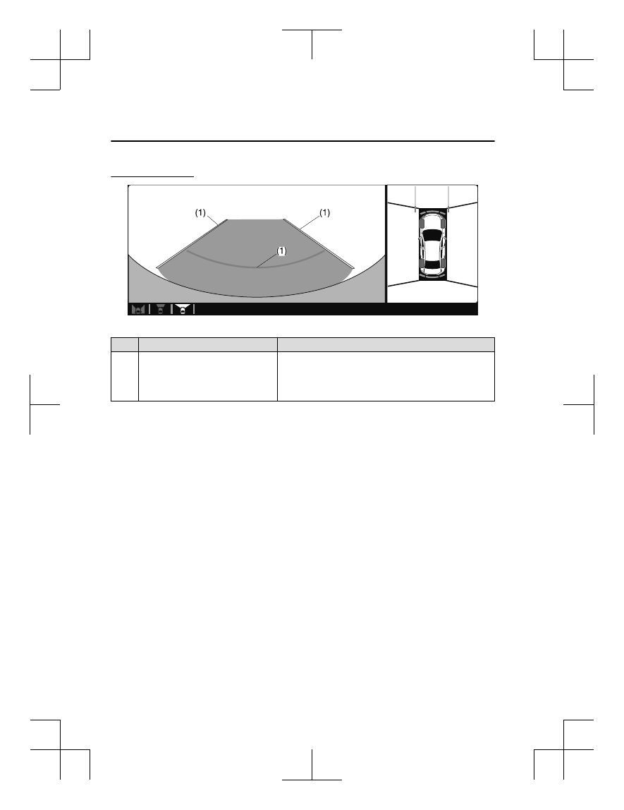
(1)

Extended vehicle width lines and dis

tance guide lines (blue & red)

Indicates the approximate width of the vehicle and the distance
(from front end of bumper) in front of the vehicle.

The red lines indicate the points up to about 0.5 m (19 in)
from the front end of the bumper.

NOTE

The front wide view screen displays the image in front of the vehicle at a wide angle and
corrects the image to help detect approaching obstructions from the side. Therefore, it
differs from the actual view.

Side View

Use the side view to assist in checking the safety of the surrounding area when accelerating
from a stop, parking, or stopping the vehicle.

When Driving

i-ACTIVSENSE

4-242

Display range

Target object

Viewing the screen


Display/Icon

Content

(1)

Projected vehicle path lines (yellow)

Indicates the approximate projected path of the vehicle.
Moves in conjunction with the steering wheel operation.
The projected vehicle path lines (yellow) indicate the path the
inner side of the vehicle is expected to travel.

(2)

Vehicle parallel guide lines (blue)

Indicates the approximate vehicle width including the door
mirrors.

When Driving

i-ACTIVSENSE

4-243

Display/Icon

Content

(3)

Vehicle front end guide lines (blue)

Indicates the point about 0.25 m (9.8 in) from the front edge
of the vehicle (front edge of the bumper).

NOTE

The setting can be changed so that the projected vehicle path lines are not displayed.
Refer to the Settings section in the Mazda Connect Owner's Manual.

How to use the projected vehicle path line function

(Screen display)

(Actual condition)

 
Make sure that there are no obstructions within the projected vehicle path lines.
Turn the steering wheel so that the projected vehicle path lines travel inside of the
obstruction (A), and drive the vehicle forward until it passes the obstruction.
If the projected vehicle path lines are on an obstruction (B) or outside of the obstruction (C),
the vehicle may contact the obstruction when turning the vehicle sharply.

CAUTION

The parking sensor detection range has limitations. For example, obstructions closing in
from the side and objects short in height may not be detected. Always confirm the safety
around the vehicle visually when driving.
For details, refer to the parking sensor obstruction detection indication and warning sound.

When Driving

i-ACTIVSENSE

4-244

Refer to Parking Sensor System on page 4-302.

Do not turn the steering wheel any more until the vehicle has passed the obstruction, even
if the obstruction is not visible on the side view image. If the steering wheel is turned even
more, the vehicle may contact the obstruction if it is turned sharply.

NOTE

Because there might be a difference between the image displayed on the screen and the
actual conditions, always check the safety of the surrounding area using the mirrors and
directly with your eyes when driving.

Even though the object displayed on the screen, such as a road curb or a division line of a
parking space, and the vehicle parallel guide lines appear parallel, they may not actually
be parallel.

Top View/Rear View

Use the top view/rear view to assist in checking the safety of the surrounding area when
accelerating from a stop, parking, or stopping the vehicle.

Range of displayed screen image

Target object

NOTE

In the top view screen, the areas in black at the front and rear of the vehicle image and the
seams where each of the camera images merge are blind spots.

Because images displayed in the top view screen are processed from each camera, the top
view screen may display in the following ways.

When Driving

i-ACTIVSENSE

4-245

If an image containing an object with a conspicuous color is picked up by any of the
cameras, the screen area for each camera may be affected and it may display in that
color.

Obstructions displayed in the rear view may not display on the top view screen.

If the position or angle of each camera changes due to tilting of the vehicle, the image
may appear distorted.

Lines on the road may appear distorted at the seams where each of the camera images
merge.

The screen area for each camera may appear bright/dark depending on the illumination
level around any of the cameras.

Viewing the screen


Display/Icon

Content

(1)

Tire icon

Indicates the tire direction. Moves in conjunction with the
steering wheel operation.

(2)

Projected vehicle path lines (yellow &
red)

Indicates the approximate projected path of the vehicle.
Moves in conjunction with the steering wheel operation.
a) Indicates the path where the edge of the rear bumper is ex

pected to travel.
b) Indicates the path where the outer side of the vehicle is ex

pected to travel.

(3)

Extended vehicle width lines (blue)

These guide lines indicate the approximate width of the vehi

cle.

(4)

Projected vehicle path distance guide
lines (yellow & red)

These guide lines indicate the approximate distance to a point
measured from the rear of the vehicle (from the end of the
bumper).

The red line indicates the point about 0.5 m (19 in) from the
rear end of the bumper.

The yellow lines indicate the points about 1.0 m (39 in) and
2.0 m (78 in) from the rear end of the bumper.

When Driving

i-ACTIVSENSE

4-246

NOTE

The setting can be changed so that the projected vehicle path lines are not displayed.
Refer to the Settings section in the Mazda Connect Owner's Manual.

How to use the projected vehicle path line function

CAUTION

The front of the vehicle swings out wide when turning the steering wheel while reversing.
Maintain sufficient distance between the vehicle and an obstruction.

The parking sensor detection range has limitations. For example, obstructions closing in
from the side and objects short in height may not be detected. Always confirm the safety
around the vehicle visually when driving.
For details, refer to the parking sensor obstruction detection indication and warning sound.
Refer to Parking Sensor System on page 4-302.

NOTE

Because there might be a difference between the image displayed on the screen, such as
indicated in the following, and the actual conditions when parking, always check the
safety at the rear of the vehicle and the surrounding area directly with your eyes.

Even though the back end of the parking space (or garage) displayed on the screen and
distance guide lines appear parallel, they may not actually be parallel.

When parking in a space with a division line on only one side of the parking space, even
though the division line and the vehicle width guide line appear parallel, they may not
actually be parallel.

The following shows an example of vehicle parking with the steering wheel turned to the
left while backing up the vehicle. When backing into a parking space from the opposite
direction, the steering operation is reversed.

When Driving

i-ACTIVSENSE

4-247

1. Back the vehicle into the parking space by turning the steering wheel so that the vehicle

enters the center of the parking space.
 

(Screen display)

(Actual condition)

2. After the vehicle starts entering the parking space, stop and adjust the steering wheel so

that the distance between the vehicle width lines and the sides of the parking space on
the left and right are roughly equal, and then continue backing up slowly.

3. Once the vehicle width lines and the sides of the parking space on the left and right are

parallel, straighten the wheels and back the vehicle slowly into the parking space.
Continue checking the vehicle's surroundings and then stop the vehicle in the best

When Driving

i-ACTIVSENSE

4-248

possible position. (If the parking space has division lines, check whether the vehicle
width guide lines are parallel to them.)
 

(Screen display)

(Actual condition)

Top View/Rear Wide View

Use the top view/rear wide view to assist in checking the safety of the surrounding area
when accelerating from a stop, parking, or stopping the vehicle.

When Driving

i-ACTIVSENSE

4-249

Range of displayed screen image

Target object

NOTE

In the top view screen, the areas in black at the front and rear of the vehicle image and the
seams where each of the camera images merge are blind spots.

Because images displayed in the top view screen are processed from each camera, the top
view screen may display in the following ways.

If an image containing an object with a conspicuous color is picked up by any of the
cameras, the screen area for each camera may be affected and it may display in that
color.

Obstructions displayed in the front view may not display on the top view screen.

If the position or angle of each camera changes due to tilting of the vehicle, the image
may appear distorted.

Lines on the road may appear distorted at the seams where each of the camera images
merge.

The screen area for each camera may appear bright/dark depending on the illumination
level around any of the cameras.

When Driving

i-ACTIVSENSE

4-250

Viewing the screen


Display/Icon

Content

(1)

Extended vehicle width lines and dis

tance guide lines (blue & red)

These guide lines indicate the approximate width of the vehi

cle and distance to a point measured from the rear of the vehi

cle (from the end of the bumper).

The red lines indicate the points up to about 0.5 m (19 in)
from the rear end of the bumper.

NOTE

The top view/rear wide view screen displays the image at the rear of the vehicle at a wide
angle and corrects the image to help detect approaching obstructions from the side.
Therefore, it differs from the actual view.

Margin of Error Between Road Surface on Screen and Actual Road Surface

There might be some margin of error between the road surface appearing on the screen and
the actual road surface. A margin of error in the perceived distance could lead to an
accident, therefore be aware of the following conditions which can more easily produce
errors in the perceived distance.
 

The vehicle tilts due to weight of passengers and cargo.

If the vehicle is tilted, obstructions picked up by a camera can appear farther or closer than
the actual distance from the vehicle.

When Driving

i-ACTIVSENSE

4-251

Front camera

Obstruction

Margin of error

Side camera

Obstruction

Margin of error

Rear camera

Obstruction

Margin of error


There is a steep up or down grade in the road at the front or rear of the vehicle

If there is a steep up or down grade in the road at the front or rear of the vehicle,
obstructions picked up by the camera can appear farther or closer than the actual distance
from the vehicle.

When Driving

i-ACTIVSENSE

4-252

Front camera

 Actual obstruction

 Actual obstruction

A: Distance of obstruction being viewed on screen 
B: Actual distance of obstruction from vehicle

Obstruction appearing 
on screen

Obstruction appearing 
on screen

Appears further than 
actual distance

Appears closer than 
actual distance

A

A

B

B

Side camera

 Actual obstruction

 Actual obstruction

A: Distance of obstruction being viewed on screen 
B: Actual distance of obstruction from vehicle

Obstruction appearing 
on screen

Obstruction appearing 
on screen

Appears further than 
actual distance

Appears closer than 
actual distance

A

A

B

B

Rear camera

 Actual obstruction

 Actual obstruction

A: Distance of obstruction being viewed on screen 
B: Actual distance of obstruction from vehicle

Obstruction appearing on screen

Obstruction appearing 
on screen

Appears further than 
actual distance

Appears closer than 
actual distance

A

A

B

B

When Driving

i-ACTIVSENSE

4-253

NOTE

If the vehicle is on a slope, obstructions taken by the camera can appear farther or closer
than the actual distance from the vehicle.


Three-dimensional object at vehicle front or rear

Because the vehicle front end guide lines (side camera) or the distance guide lines (rear
camera) are displayed based on a flat surface, the distance to the three-dimensional object
displayed on the screen is different from the actual distance.

Side camera

(Actual condition)

(Screen display)

When Driving

i-ACTIVSENSE

4-254

Rear camera

(Actual condition)

Sensed distance on screen A > B > C

Actual distance B > C = A

(Screen display)

System Problem Indication

Center display indication

Cause

Action to be taken

“No camera signal.” is displayed

The control unit might be damaged.

Have your vehicle inspected
by an Authorized Mazda
Dealer.

Screen is pitch-black and blank

The camera might be damaged.

When Driving

i-ACTIVSENSE

4-255

Forward Sensing Camera (FSC)

*

Your vehicle is equipped with a Forward Sensing Camera (FSC). The Forward Sensing
Camera (FSC) is positioned near the rearview mirror and used by the following systems.

High Beam Control System (HBC)

Driver Attention Alert (DAA)

Lane-keep Assist System (LAS) & Lane Departure Warning System (LDWS)

Traffic Sign Recognition System (TSR)

Advanced Smart City Brake Support (Advanced SCBS)

Smart City Brake Support [Forward] (SCBS F)

Mazda Radar Cruise Control with Stop & Go function (MRCC with Stop & Go function)

Traffic Jam Assist (TJA)

Smart Brake Support (SBS)

Forward Sensing Camera (FSC)

The Forward Sensing Camera (FSC) determines the conditions ahead of the vehicle while
traveling at night and detects traffic lanes. The distance in which the Forward Sensing
Camera (FSC) can detect objects varies depending on the surrounding conditions.

WARNING

Do not modify the suspension:

If the vehicle height or inclination is changed, the system will not be able to correctly detect
vehicles ahead. This will result in the system not operating normally or mistakenly operating,
which could cause a serious accident.

CAUTION

Do not apply accessories, stickers or film to the windshield near the Forward Sensing
Camera (FSC).

When Driving

i-ACTIVSENSE

4-256

*Some models.

If the area in front of the Forward Sensing Camera (FSC) lens is obstructed, it will cause the
system to not operate correctly. Consequently, each system may not operate normally
which could lead to an unexpected accident.

Do not disassemble or modify the Forward Sensing Camera (FSC).
Disassembly or modification of the Forward Sensing Camera (FSC) will cause a malfunction
or mistaken operation. Consequently, each system may not operate normally which could
lead to an unexpected accident.

Heed the following cautions to assure the correct operation of the Forward Sensing Camera
(FSC).

Be careful not to scratch the Forward Sensing Camera (FSC) lens or allow it to get dirty.

Do not remove the Forward Sensing Camera (FSC) cover.

Do not place objects on the dashboard which reflect light.

Always keep the windshield glass around the camera clean by removing dirt or fogging.
Use the windshield defroster to remove fogging on the windshield.

Consult an Authorized Mazda Dealer regarding cleaning the interior side of the
windshield around the Forward Sensing Camera (FSC).

Consult an Authorized Mazda Dealer before performing repairs around the Forward
Sensing Camera (FSC).

The Forward Sensing Camera (FSC) is installed to the windshield. Consult an Authorized
Mazda Dealer for windshield repair and replacement.

When cleaning the windshield, do not allow glass cleaners or similar cleaning fluids to
get on the Forward Sensing Camera (FSC) lens. In addition, do not touch the Forward
Sensing Camera (FSC) lens.

When performing repairs around the rearview mirror, consult an Authorized Mazda
Dealer.

Consult an Authorized Mazda Dealer regarding cleaning of the camera lens.

Do not hit or apply strong force to the Forward Sensing Camera (FSC) or the area around
it. If the Forward Sensing Camera (FSC) is severely hit or if there are cracks or damage
caused by flying gravel or debris in the area around it, stop using the following systems
and consult an Authorized Mazda Dealer.

High Beam Control System (HBC)

Driver Attention Alert (DAA)

Lane-keep Assist System (LAS) & Lane Departure Warning System (LDWS)

Traffic Sign Recognition System (TSR)

Advanced Smart City Brake Support (Advanced SCBS)

Smart City Brake Support [Forward] (SCBS F)

Mazda Radar Cruise Control with Stop & Go function (MRCC with Stop & Go function)

Traffic Jam Assist (TJA)

Smart Brake Support (SBS)

When Driving

i-ACTIVSENSE

4-257


Content      ..     23      24      25      26     ..