Mazda 6. Manual - part 201


  Index      Mazda     Mazda 6 - service repair manual 2002 year


Search            


Content   ..  199  200  201  202   ..


Mazda 6. Manual - part 201


AUTOMATIC TRANSAXLE SHIFT MECHANISM 

K–46–3

K

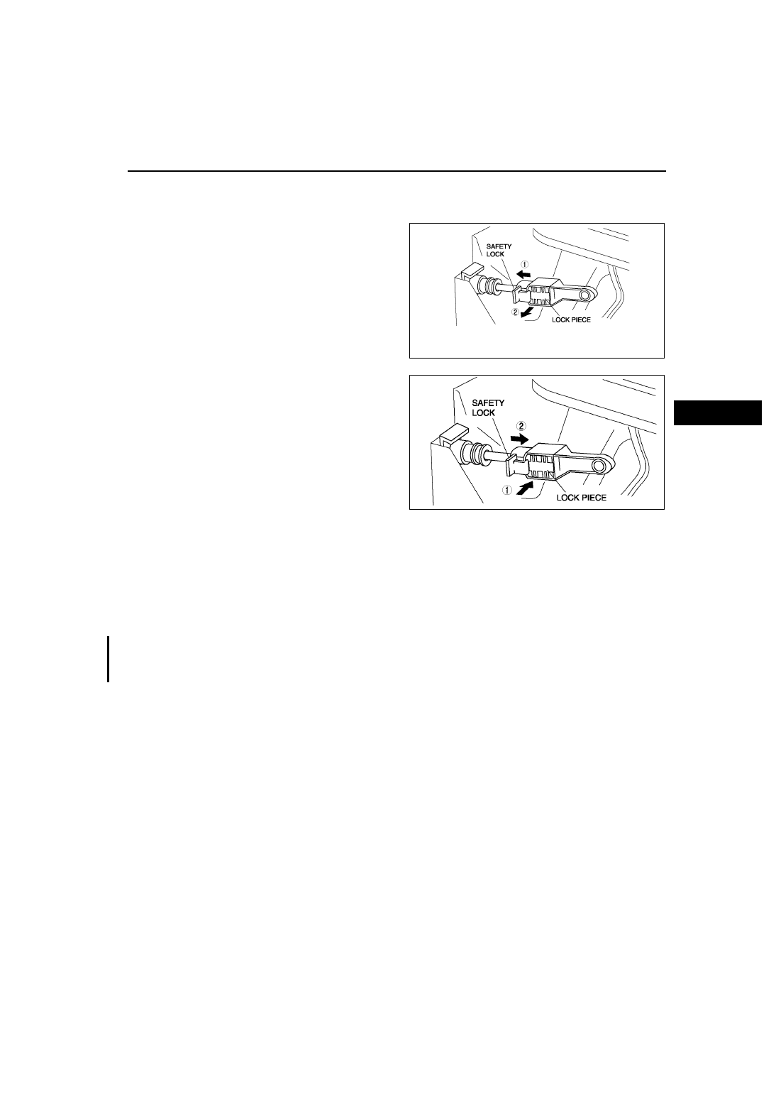
SELECTOR CABLE ADJUSTMENT

A6E561646102W02

1. Remove the center console.
2. Shift the selector lever to P position.
3. Unlock the lock piece of the selector cable 

(selector lever side) in the order shown in the 
figure.

4. Verify that the manual shaft is in P position.

5. Lock the lock piece of the selector cable (selector 

lever side) in the order shown in the figure.

6. Install the center console.
7. Shift the selector lever from P position to L range, 

and make sure that there are no other 
components in that area to interfere with the lever.

End Of Sie

SELECTOR LEVER REMOVAL/INSTALLATION

A6E561646102W03

1. Disconnect the negative battery cable. 
2. Remove battery and battery tray.
3. Remove the air cleaner compornent. (See 

F–10 INTAKE-AIR SYSTEM REMOVAL/INSTALLATION

.)

4. Remove the console.
5. Remove the dashboard compleat.

(See 

S–82 DASHBOARD REMOVAL/INSTALLATION

.) 

6. Remove the SAS control module.

(See 

T–124 SAS UNIT REMOVAL/INSTALLATION

.) 

7. Remove the climate control unit. (See 

U–44 CLIMATE CONTROL UNIT REMOVAL

.) (See 

U–45 CLIMATE 

CONTROL UNIT INSTALLATION

.)

8. Remove the rear heat duct. (See 

U–23 REAR HEAT DUCT REMOVAL/INSTALLATION

.)

9. Remove in the order shown in the figure.

10. Remove the battery, battery tray and battery bracket.

End Of Sie

A6E5616W003

A6E5616W004

AUTOMATIC TRANSAXLE SHIFT MECHANISM 

K–47

K

KAUTOMATIC TRANSAXLE

1. Install in the reverse order of removal.

.

AUTOMATIC TRANSAXLE SHIFT MECHANISM

A6E5616W005

1

Column cover(with key interlock)

2

Clip(with key interlock)

3

Clip(with key interlock)

4

Interlock cable(with key interlock)
(See 

K–49 Interlock Cable Installation Note

.)

5

Selector cable
(See 

K–48 Selector Cable Removal Note

.)

(See 

K–48 Selector Cable Installation Note

.)

6

Selector  lever

K–48

AUTOMATIC TRANSAXLE SHIFT MECHANISM 

Selector Cable Removal Note

1. Remove the clip.
2. Remove the selector cable.

Selector Cable Installation Note

1. Install the selector cable to the selector lever certainly.
2. Install the selector cable to the bracket certainly.

Note

• Step 3, 4 is for the selector cable 

replacement only.

3. Verify that the selector lever is in P position.

4. Lock the lock piece of the selector cable (selector 

lever side) in the order shown in the figure.

5. Verify that the manual shaft is in P position.

A6E5616W006

A6E5616W020

A6E5616W004

A6E5616W007

AUTOMATIC TRANSAXLE SHIFT MECHANISM 

K–49

K

Caution

• Bending the selector cable in the manner 

shown in the figure will damage the cable 
and it may become loose when shifted. 
When installing the selector cable, hold it 
straight.

Note

• Install the selector lever to the manual shaft 

lever with the spring side of the selector 
cable end facing the front of the vehicle.

6. Install the selector lever to the manual shaft lever 

so that no load acts on the selector cable.

7. Confirm that the tip of the manual shift lever projects out of the end of the selector cable.
8. Install the selector cable to the selector cable securely bracket.

Interlock Cable Installation Note

1. Install the interlock cable as shown in the figure.

Caution

• Position the sponge protector so that it is 

not crushed or squeezed by the SAS unit.

• If the interlock and selector cables cross 

over each other, position the interlock 
cable to pass over the selector cable.

2. Push the snap pin (or a 

φ1.5 round bar or 

simular.) into hole A by fully pushing the slider pin 
in.

3. Push the snap pin into hole B and hole C of the 

lock unit until it passes through.

4. Disconnect the brake switch connector.
5. Remove the brake switch. (See 

P–9 BRAKE 

PEDAL REMOVAL/INSTALLATION

.)

6. Install the new brake switch. (See 

P–9 BRAKE 

PEDAL REMOVAL/INSTALLATION

.)

Caution

• Do not connect the brake switch 

connector until the interlock cable is 
installed.

7. With the slider pin pressed, slide the lock unit to 

fix the lock unit hook into the bracket hole 
securely as shown in the figure.

Caution

• Allowing the interlock cable to be bent or 

twisted during installation can affect the 
lock unit operation.

8. Rotate the slider pin to release the lock, and verify 

that the it slides freely.

A6E5616W008

SAS UNIT WIRING HARNESS

SAS UNIT

SELECTOR 
CABLE

INTERLOCK 
CABLE

SPONGE PROTECTOR

A6E5616L001

SLIDER PIN

INTERLOCK
CABLE

BRAKE SWITCH

A

B

C

LOCK UNIT

CHU0514W012

SLIDER PIN

LOCK UNIT

BRACKET

BHE0514W007


Content   ..  199  200  201  202   ..