Mazda 6. Manual - part 202
K–50
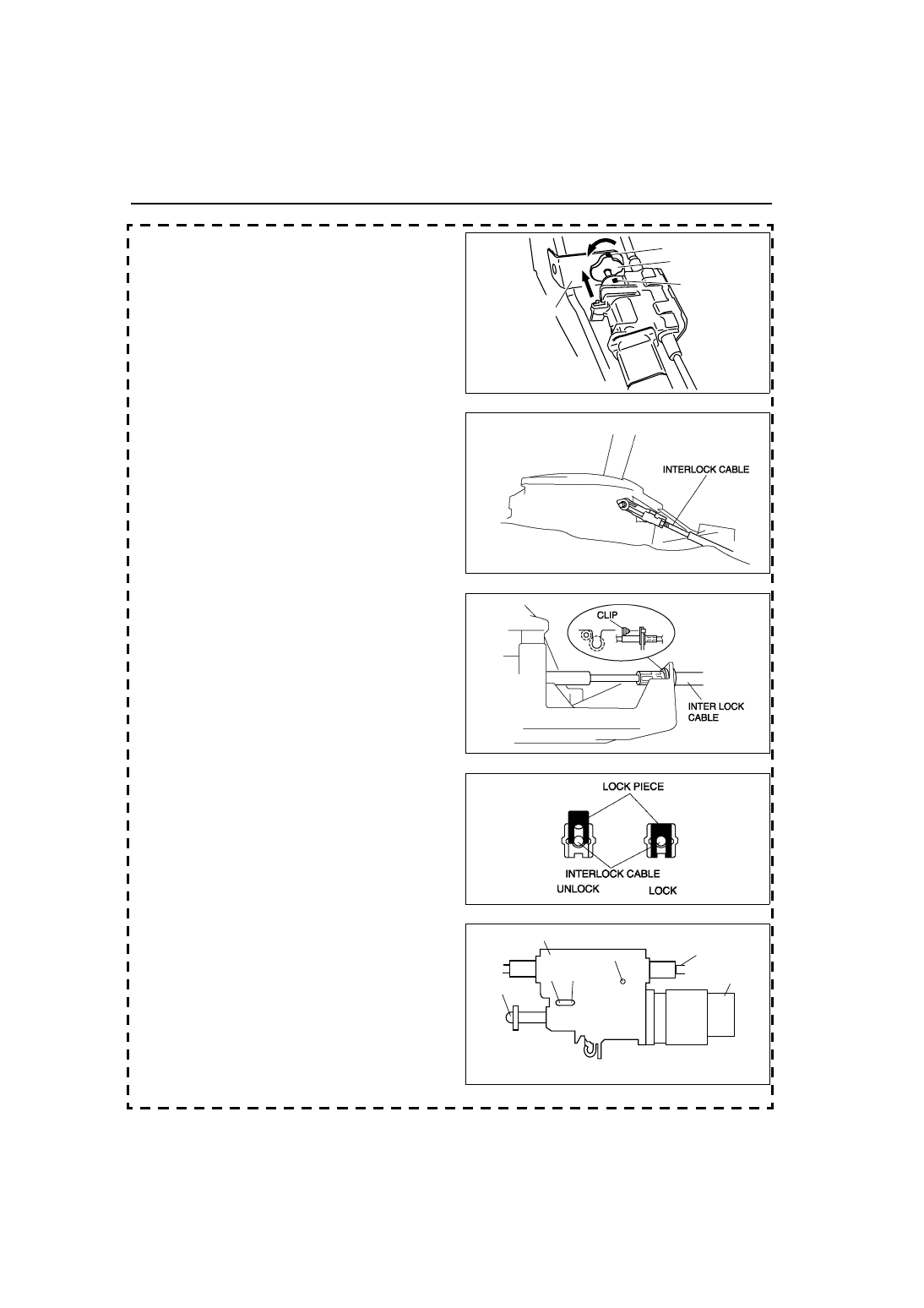
AUTOMATIC TRANSAXLE SHIFT MECHANISM
9. Pull the slider pin outward until it contacts the
brake pedal stopper rubber and rotate the slider
pin to lock.
10. Verify that the shift the selector lever in P position.
11. Install the interlock cable end onto the cam pin on
the selector lever.
12. Fit the interlock cable in the U–groove in the
selector lever base plate, and install the clip.
13. Press the interlock cable lock piece in until it is
locked.
Caution
• Applying a load to the interlock cable
while pressing the lock piece in can
affect the lock unit operation.
14. Remove the snap pin from the lock unit hole A, B
and C.
End Of Sie
STOPPER
RUBBER
SLIDER PIN
MARKING
MARKING
BHE0514W011
A6E5616W010
A6E5616W011
A6E5616W012
SLIDER PIN
INTERLOCK
CABLE
BRAKE SWITCH
A
B
C
LOCK UNIT
CHU0514W012