Mazda 6. Manual - part 199
 

  Index      Mazda     Mazda 6 - service repair manual 2002 year


Search            


Content   ..  197  198  199  200   ..


Mazda 6. Manual - part 199


AUTOMATIC TRANSAXLE 

K–41

K

2. Align the marks, and slide the oil hose onto the oil 

pipe until it is fully seated as shown.

Note

• If reusing the hose, install the new hose 

clamp exactly on the mark left by the 
previous hose camp.Then apply force to the 
hose clamp in the direction of the arrow in 
order to fit the clamp in the place.

3. Install the new hose clamp onto the hose.
4. Verify that the hose clamp does not interfere with 

any other components.

End Of Sie

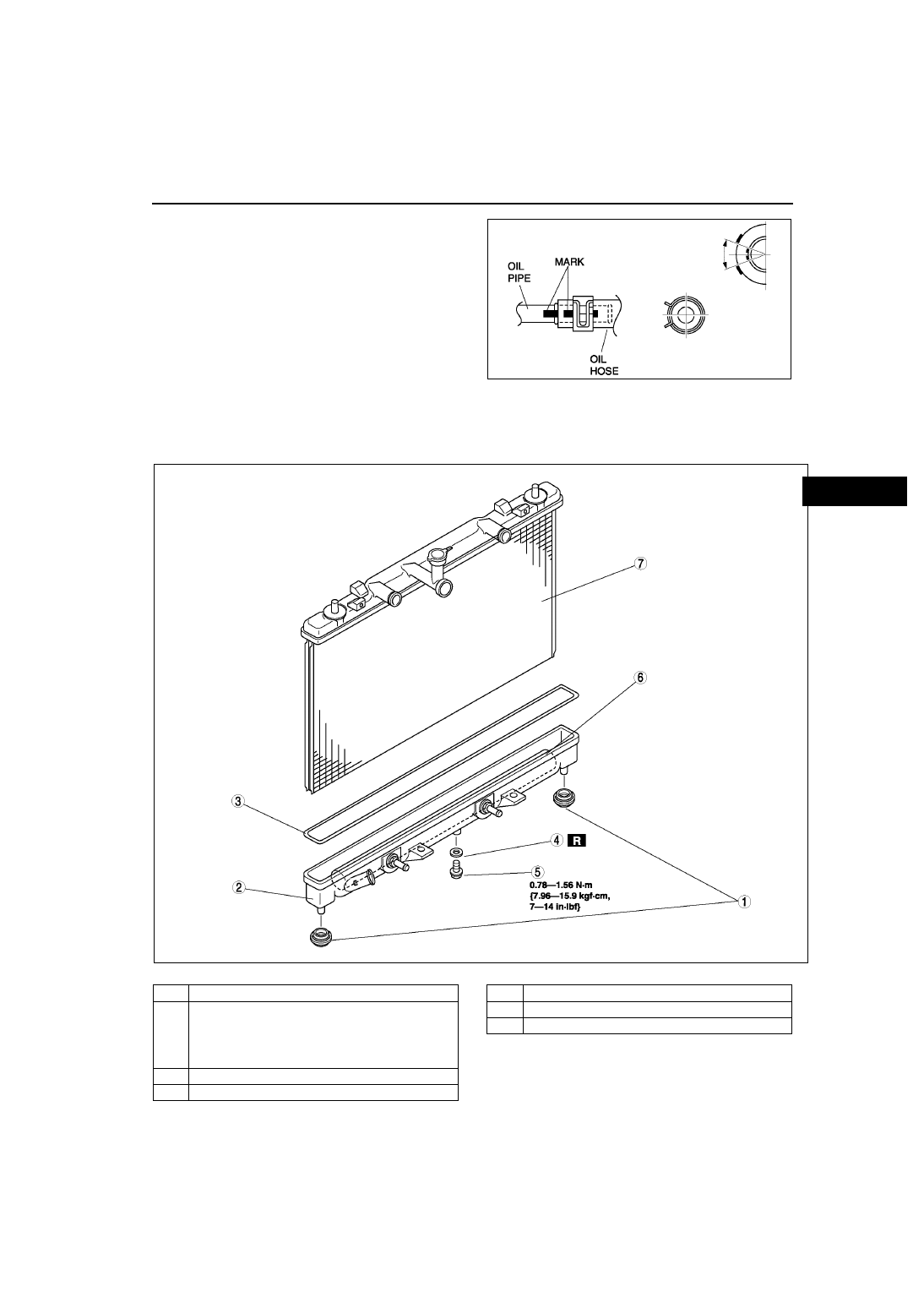
OIL COOLER DISASSEMBLY/ASSEMBLY

A6E561419900W03

1. Disassemble in the order indicated in the table.
2. Assemble in the reverse order of disassembly.

.

A6E5614W071

A6E5614W072

1

Mount rubber

2

Radiator outer tank (in tank oil cooler)
(See 

K–42 Radiator Outer Tank (In Tank Oil Cooler) 

Removal Note

.)

(See 

K–42 Radiator Outer Tank (In Tank Oil Cooler) 

Installation Note

.)

3

O-ring

4

Washer

5

Drain  plug

6

ATF cooler

7

Radiator

K–42

AUTOMATIC TRANSAXLE 

Radiator Outer Tank (In Tank Oil Cooler) Removal Note

1. Inspect the height of the header tabs.
2. Insert the end of a medium tip screwdriver 

between the end of the header tab and the outer 
tank.

Note

• Do not open more tabs than necessary for 

tank removal.

3. Pivot the screwdriver to pry the tab away from the 

tank and repeat the procedure for each tab.

4. Remove the radiator outer tank and O-ring 

(gasket) from the core header when all of the tabs 
are opened.

Note

• If any header tabs are missing from the core, 

replace the radiator.

5. Inspect the gasket surface of the radiator core 

header to ensure it is clean and free of foreign 
material or damage.

6. Inspect the radiator outer tank for warping. If it is 

warped, replace radiator tank.

Radiator Outer Tank (In Tank Oil Cooler) Installation Note

1. Install a new O-ring and ensure it is not twisted.

Note

• The old O-ring must be replaced.

2. Position the radiator tank in the original direction 

to the core using care not to scratch the tank 
sealing surface with the header tabs.

Note

• Step 3 will set jaw opening to the correct 

specification.

3. With the jaws of locking-type pliers (vise grips) 

closed and locked, turn the adjusting screw to 
position the jaws against the drill bit with the 
diameter measured (height) in removal procedure 
1. Tighten the lock nut on the adjusting screw 
against the handle to lock the adjustment in place.

A6E5614W073

A6E5614W074

A6E5614W075

A6E5614W093

AUTOMATIC TRANSAXLE 

K–43

K

4. Squeeze the header tabs down in order as shown 

against the lip of radiator outer tank base with 
locking-type pliers while rotating the pliers toward 
the tank.

5. Verify the height of the header tabs is same as 

the height before removal.

6. Inspect for leakage from radiator. (See 

E–4 

ENGINE COOLANT LEAKAGE INSPECTION

.)

End Of Sie

DRIVE PLATE REMOVAL/INSTALLATION

A6E561419020W01

1. Remove the transaxle.(See 

K–29 AUTOMATIC TRANSAXLE REMOVAL/INSTALLATION

.)

2. Remove in the order indicated in the figure.
3. Install in the reverse order of removal.

.

A6E5614W076

A6E5614W073

1

Drive plate mounting bolts
(See 

K–44 Drive Plate Mounting Bolts Removal 

Note

.)

2

Adapter

3

Drive plate
(See 

K–44 Drive Plate Installation Note

.)

A6E5614W078

K–44

AUTOMATIC TRANSAXLE 

Drive Plate Mounting Bolts Removal Note

1. Set the SST or equivalent against the drive plate.
2. Remove the bolts and the drive plate.

Drive Plate Installation Note

Caution

• If the bolts are reused, remove the oil sealant from the bolt threads. Tightening a bolt that has old 

sealant on it can cause thread damage.

1. Remove the sealant from the bolts hole in the crankshaft and from the drive plate mounting bolts.

Note

• If all the previous sealant cannot be removed from a bolt, replace the bolts. 

• Do not apply sealant if a new bolts is used.

2. Install the drive plate.
3. Install the adapter.
4. Apply sealant to the drive plate mounting bolts and install them.
5. Set the SST or equivalent against the drive plate.

Caution

• When installing sealant covered bolts, tighten them immediately. Leaving these bolts in a half 

installed condition could cause them to be stuck that way, due to the natural hardening or the 
sealant.

6. Tighten the drive plate mounting bolts in two or 

three steps in the order shown.

Tightening torque

108—1116 N·m {11.0—11.8 kgf·m, 80—85 

ft·lbf}

7. Install the transaxle. (See 

K–29 AUTOMATIC 

TRANSAXLE REMOVAL/INSTALLATION

.)

End Of Sie

A6E5614W079

A6E5614W081


Content   ..  197  198  199  200   ..