Lexus SC300 / Lexus SC400. Manual - part 321
 

  Index      Lexus     Lexus SC300 / Lexus SC400 - service repair manual


Search            


Content   ..  319  320  321  322   ..


Lexus SC300 / Lexus SC400. Manual - part 321


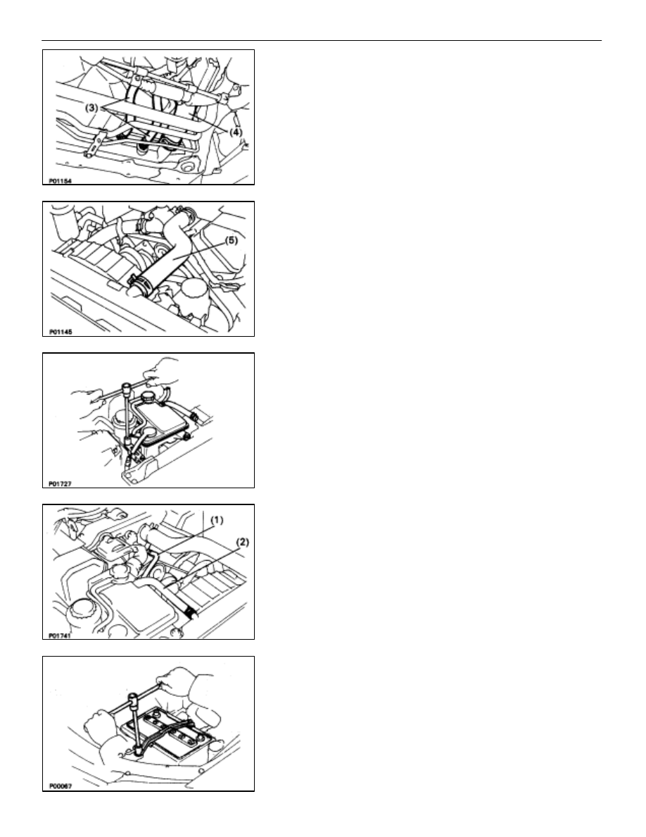
(3) Two oil cooler hoses (for A/T) to radiator.
(4) Lower radiator hose to radiator

(5) Upper radiator hose to radiator

7. INSTALL 

RADIATOR 

RESERVOIR 

TANK

(a)  Install the reservoir tank to the reservoir tank bracket.
(b)  Install the reservoir tank bracket with two bolts.

Torque: 4.9 N

m (50 kgf

cm, 43 in.

lbf)

(c)  Connect the following hoses:

(1) Reservoir hose to water inlet housing
(2) Reservoir hose to radiator

(d)  Connect the coolant level sensor connector.

8. INSTALL 

BATTERY

CO–20

COOLIING SYSTEM

Radiator

9. 

FILL ENGINE WITH COOLANT (See page 

CO–7

)

10.  FILL COOLING FAN RESERVOIR TANK WITH FLUID

(See pages 

CO–23

 and 24)

11.  CHECK AUTOMATIC TRANSMISSION FLUID LEVEL

(See page 

MA–11

)

NOTICE: Do not overfill.

12.  START ENGINE AND CHECK FOR LEAKS
13.  INSTALL ENGINE UNDER COVER

COOLIING SYSTEM

Radiator

CO–21

(3)

 Upper radiator hose or radiator

(4)

 Reservoir hose to radiator

5. INSTALL 

BATTERY

6. 

FILL ENGINE WITH COOLANT (See page 

CO–5

)

Capacity (w/ Heater):

M/T 8.5 liters (9.0 US qts, 7.5 Imp. qts)

A/T 8.4 liters (8.9 US qts, 7.4 Imp. qts)

7. (A/T)

CHECK AUTOMATIC TRANSMISSION FLUID LEVEL (See page

MA–11

)

NOTICE: Do not overfill.

8. 

START ENGINE AND CHECK FOR LEAKS

9. 

INSTALL ENGINE UNDER COVER

SERVICE SPECIFICATIONS

SERVICE DATA

Thermostat

Valve opening temperature

80–84

°

c

176–183

°

F

Valve lift

at 95

°

C (203

°

F)

8.5 mm

0.335 in.

Radiator cap

Relief valve opening pressure

STD

74–103 kPa
(0 75 1 05 k f/

10 7 14 9

i)

(0.75–1.05 kgf/cm, 10.7–14.9 psi)

Limit

59 kPa

0.6 kgf/cm

2

8.5 psi

TORQUE SPECIFICATIONS

Part tightened

N


m

kgf


cm

ft


lbf

Engine drain plug X Cylinder block

29

300

22

Water pump X Cylinder block

21

210

15

Water pump X Water by–pass pipe

21

210

15

Water by–pass outlet X Cylinder head

  8.8

90

78 in.


lbf

Water inlet X Water pump

  8.8

90

78 in.


lbf

Oil cooler X Radiator lower tank (A/T)

  8.3

85

74 in.


lbf

Oil cooler X Pipe (A/T)

15

150

11

Radiator fan shroud X Radiator

  4.9

50

43 in.


lbf

Radiator X Body

12

120

9

COOLING SYSTEM

Radiator, Service Specifications

CO–21

ELECTRONICALLY CONTROLLED HYDRAULIC COOLING FAN

Description

In this way system, the cooling fan ECU controls the hydraulic pressure acting on the hydraulic motor, thus

controlling the speed of the cooling fan steplessly in response to the condition of the engine and air conditioner.

Operation

The hydraulic pump is driven by a drive belt (V–ribbed belt). The solenoid valve adjusts the volume of oil

sent from the hydraulic pump to the hydraulic motor which drives the fan directly, thereby controlling the fan
speed.

Oil which has passed through the hydraulic motor is cooled by the oil cooler before returning to the reservoir

tank.

The solenoid valve is controlled by the computer in accordance with the E/G rpm, water temp. and A/C

signals.

CO–22

COOLIING SYSTEM

Electronically Controlled Hydraulic
Cooling Fan (Description, Operation)


Content   ..  319  320  321  322   ..