Lexus SC300 / Lexus SC400. Manual - part 30
 

  Index      Lexus     Lexus SC300 / Lexus SC400 - service repair manual


Search            


Content   ..  28  29  30  31   ..


Lexus SC300 / Lexus SC400. Manual - part 30


ÑÑÑÑÑÑÑÑÑÑÑÑÑÑÑÑÑÑÑÑÑÑÑÑÑÑÑÑÑÑÑÑÑÑÑÑ

ÑÑÑÑÑÑÑÑÑÑÑÑÑÑÑÑÑÑÑÑÑÑÑÑÑÑÑÑÑÑÑÑÑÑÑÑ

ÑÑÑÑÑÑÑÑÑÑÑÑÑÑÑÑÑÑÑÑÑÑÑÑÑÑÑÑÑÑÑÑÑÑÑÑ

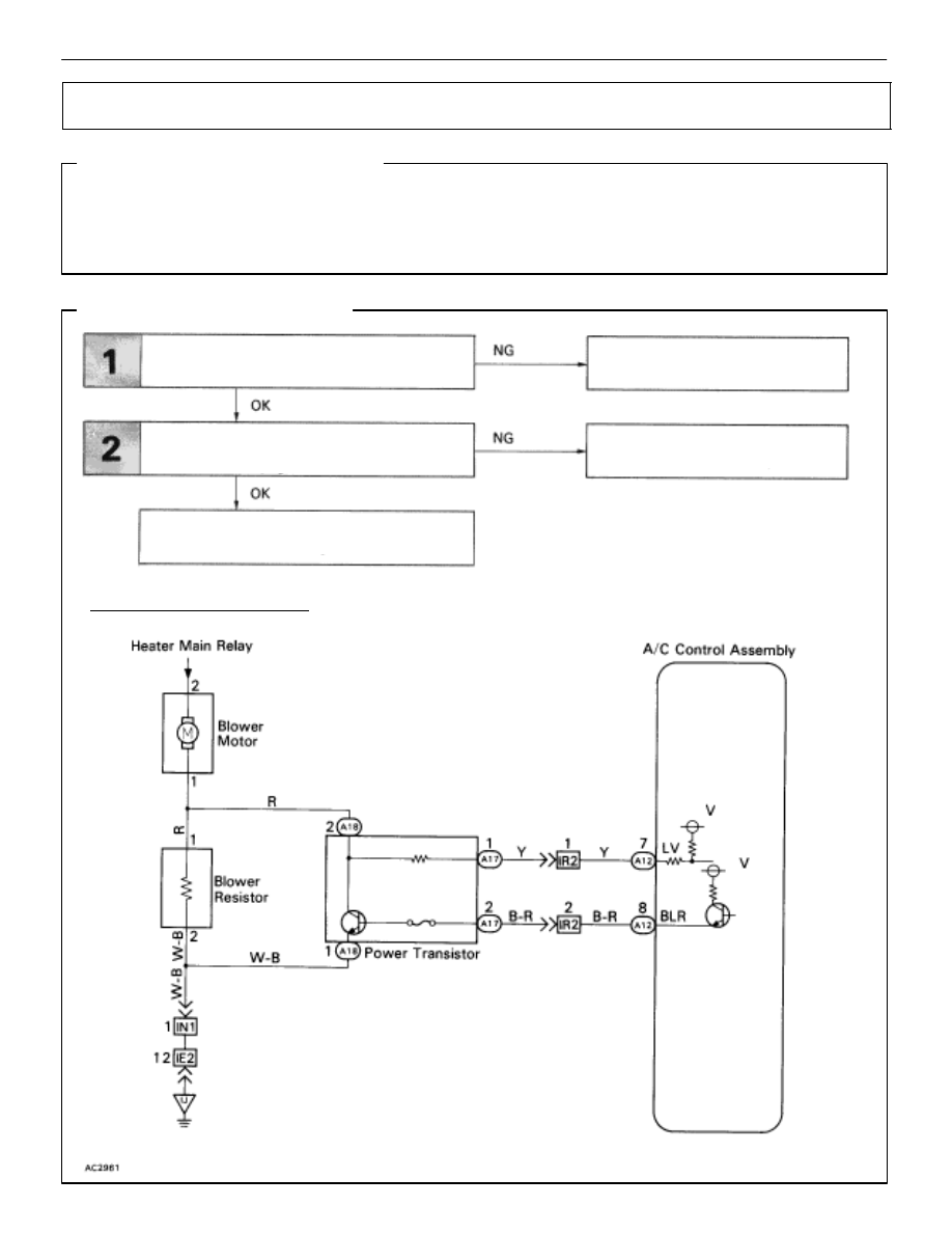
Power Transistor Circuit

CIRCUIT DESCRIPTION

The air conditioner control assembly controls the blower speed by varying the voltage at terminal BLW
which applies the base current to the power transistor.
The air conditioner control assembly also monitors the power transistor collector voltage at terminal VM,
to control blower air volume precisely.

DIAGNOSTIC CHART

WIRING DIAGRAM

Check power transistor.

Check harness and connector between air

conditioner control assembly and power

transistor (See page 

IN–27

).

Proceed to next circuit inspection
shown on matrix chart (See page 

AC-36

).

Replace power transistor.

Repair or replace harness or

connector.

AC–78

AIR CONDITIONING SYSTEM

Troubleshooting

Check power transistor.

(1)

Remove  cooling unit (See page 

BO-107

).

(2)

Disconnect power transistor connector.

(1)

Check test bulb lights up when battery and 
resistor are connected to power transistor
connector as left illustration shows.

(2)

Measure resistance between terminal 2 and 3

(1)

The bulb lights up.

(2)

Resistance:     2.0– 2.4


Replace  power transistor.

Check for open and short in harness and connector between air
conditioner control assembly and power transistor (See page 

IN-27

).

Repair or replace  harness or connector.

Proceed to next circuit inspection shown on matrix
chart  (See page 

AC-36

).

INSPECTION PROCEDURE

AIR CONDITIONING SYSTEM

Troubleshooting

AC–79

ÑÑÑÑÑÑÑÑÑÑÑÑÑÑÑÑÑÑÑÑÑÑÑÑÑÑÑÑÑÑÑÑÑÑÑÑ

ÑÑÑÑÑÑÑÑÑÑÑÑÑÑÑÑÑÑÑÑÑÑÑÑÑÑÑÑÑÑÑÑÑÑÑÑ

ÑÑÑÑÑÑÑÑÑÑÑÑÑÑÑÑÑÑÑÑÑÑÑÑÑÑÑÑÑÑÑÑÑÑÑÑ

Blower Motor Circuit

CIRCUIT DESCRIPTION

This is the power source for the blower motor.

DIAGNOSTIC CHART

WIRING DIAGRAM

Check blower motor.

Check harness and connector between battery
and blower motor, blower motor and body ground
(See page IN–37).

Check blower resistor.

Replace blower motor.

Replace blower motor.

Replace blower resistor.

Repair or replace harness or

connector.

Proceed to next circuit inspection

shown on matrix chart (See page 

AC-36

).

AC–80

AIR CONDITIONING SYSTEM

Troubleshooting

 Check blower motor.

Remove blower motor.(See page 

AC-129

).

Connect positive 


 lead connected to terminal 2 of

blower motor connector, negative 


 lead to 

terminal 1.

Blower motor operates smoothly.

Replace blower motor.

Check blower  resistor.

Disconnect blower resistor connector.

Measure resistance between terminals 1 and 2 of
blower resistor connector.

Resistance:

2.6 – 3.0 


Replace blower resistor.

Check for open short in harness and connector between battery
and blower motor, blower motor and body ground (See page 

IN-27

)

Repair or replace harness or connector.

Proceed to next circuit inspection shown on
matrix chart (See page 
AC-36).

INSPECTION PROCEDURE

AIR CONDITIONING SYSTEM

Troubleshooting

AC–81


Content   ..  28  29  30  31   ..