Lexus SC300 / Lexus SC400. Manual - part 28
 

  Index      Lexus     Lexus SC300 / Lexus SC400 - service repair manual


Search            


Content   ..  26  27  28  29   ..


Lexus SC300 / Lexus SC400. Manual - part 28


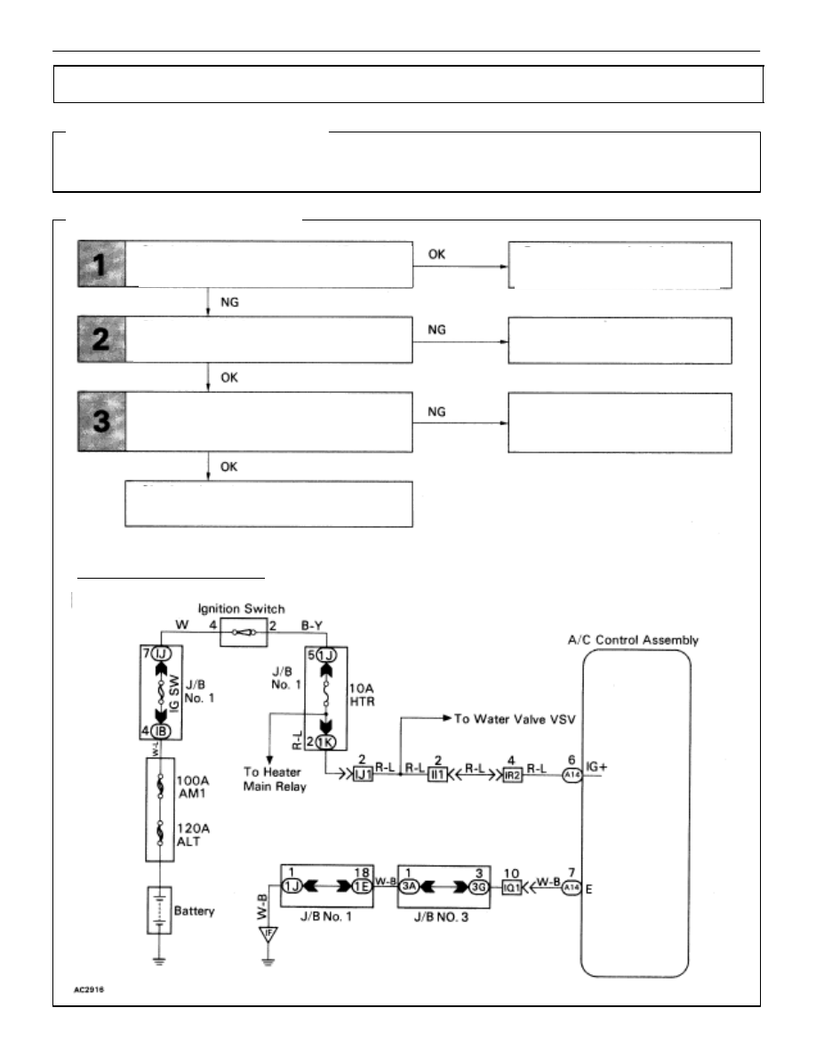
IG Power Source Circuit

CIRCUIT DESCRIPTION

This is the power source for the air conditioner control assembly (contains the A/C control assembly)
and servomotor, ect.

DIAGNOSTIC CHART

WIRING DIAGRAM

Check voltage between terminals IG+ and E

of  air conditioner control assembly 

connector.

Check continuity between terminal E of air

conditioner control assembly and 

body ground.

Check HTR fuse.

Check harness and repair and connector be-

tween air conditioner control assembly and

battery

Proceed to next circuit inspection

shown on matrix chart (See page

AC-36

).

Check for short in all the harness

and components connected to

the HTR fuse (See attached wir-

ing  diagram).

Repair or replace harness or

connector.

AC–70

AIR CONDITIONING SYSTEM

Troubleshooting

Check  voltage between terminals IG+ and  E of air conditioner control
assembly  connector.

(1)

Remove console upper panel.(See page

BO-111

).

(2)

Remove A/C control assembly with connec–
tors still connected.

(3)

Turn ignition switch ON.

Measure voltage between terminals IG+ and E of air
conditioner control assembly.

Voltage:

10 –14 V

Proceed to next circuit inspection shown on matrix
chart (See page 

AC-36

).

Check  continuity between terminals  E of air conditioner control assem-
bly and body ground.

Measure resistance between terminals E of air condi-
tioner control assembly and body ground.

Resistance:


 or less

Repair or replace  harness or connector.

Remove HTR fuse from J/B No. 1.

Check continuity of HTR fuse

Continuity

Check HTR fuse.

Check for short in all the harness and 
components connected to the HTR fuse
See attached wiring diagram).

Check and repair harness and connector between  air conditioner control assembly and battery.

INSPECTION PROCEDURE

AIR CONDITIONING SYSTEM

Troubleshooting

AC–71

ACC Power Source Circuit

CIRCUIT DESCRIPTION

This circuit supplies power to the air conditioner control assembly (contains the A/C control assembly).

DIAGNOSTIC CHART

WIRING DIAGRAM

Check voltage between terminals ACC of  air

conditioner control assembly connector

and body ground.

Check RADIO No. 2 fuse.

Check and repair  harness  and connector

between air conditioner control assembly

and battery.

Proceed to next circuit inspection

shown on matrix chart (See page

AC-36

).

Check for short in all the harness

and components connected to

the RADIO No. 2 fuse (See 

attached wiring diagram).

AC–72

AIR CONDITIONING SYSTEM

Troubleshooting

Check  voltage between terminals ACC of air conditioner control 
assembly connector and body ground.

(1)

Remove console upper panel.(See page
 

BO-111

).

(2)

Remove A/C control assembly with connec–
tors still connected.

(3)

Turn ignition switch ON.

Measure voltage between terminals ACC of air  
conditioner control assembly connector and body
ground.

Voltage:

10 – 14 V

Proceed to next circuit inspection shown on matrix
chart (See page 

AC-36

).

Check RADIO No. 2 fuse.

Remove RADIO No. 2 fuse from J/B No. 1.

Check continuity of RADIO No. 2 fuse.

Continuity.

Check for short in all the harness and 
components connected to the RADIO No. 2
fuse (See attached wiring diagram).

Check and repair harness and connector between  air conditioner control assembly and battery.

INSPECTION PROCEDURE

AIR CONDITIONING SYSTEM

Troubleshooting

AC–73


Content   ..  26  27  28  29   ..