Lexus SC300 / Lexus SC400. Manual - part 31
 

  Index      Lexus     Lexus SC300 / Lexus SC400 - service repair manual


Search            


Content   ..  29  30  31  32   ..


Lexus SC300 / Lexus SC400. Manual - part 31


ÑÑÑÑÑÑÑÑÑÑÑÑÑÑÑÑÑÑÑÑÑÑÑÑÑÑÑÑÑÑÑÑÑÑÑÑ

ÑÑÑÑÑÑÑÑÑÑÑÑÑÑÑÑÑÑÑÑÑÑÑÑÑÑÑÑÑÑÑÑÑÑÑÑ

ÑÑÑÑÑÑÑÑÑÑÑÑÑÑÑÑÑÑÑÑÑÑÑÑÑÑÑÑÑÑÑÑÑÑÑÑ

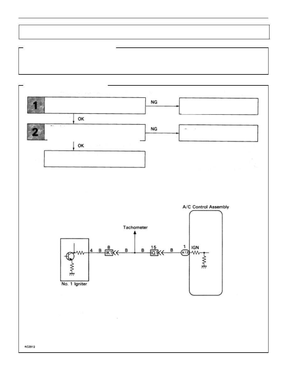
Igniter Circuit

CIRCUIT DESCRIPTION

The air conditioner control assembly monitors the engine speed through signals sent from the igniter.
The air conditioner control assembly uses these signals and compressor speed signals to detect the
compressor lock condition.

DIAGNOSTIC CHART

WIRING DIAGRAM

Check operation of tachometer.

Check harness and connector between air
conditioner control assembly and igniter 
(See page 

IN-27

).

Proceed to combination meter 
troubleshooting (See page 

BE-125

).

Proceed to next circuit inspection

shown on matrix chart (See page 

AC-36

).

Repair or replace harness or

connector.

AC–82

AIR CONDITIONING SYSTEM

Troubleshooting

Check power transistor.

Check  that the tachometer operates normally.

Proceed to combination meter trou-

bleshooting (See page 

BE-125

).

Proceed to next circuit inspection shown on matrix
chart (See page 

AC-36

).

Repair or replace harness or connector.

Check for open and short in harness and connector between air
conditioner control assembly and igniter (See page 

IN-27

).

INSPECTION PROCEDURE

AIR CONDITIONING SYSTEM

Troubleshooting

AC–83

ÑÑÑÑÑÑÑÑÑÑÑÑÑÑÑÑÑÑÑÑÑÑÑÑÑÑÑÑÑÑÑÑÑÑÑÑ

ÑÑÑÑÑÑÑÑÑÑÑÑÑÑÑÑÑÑÑÑÑÑÑÑÑÑÑÑÑÑÑÑÑÑÑÑ

ÑÑÑÑÑÑÑÑÑÑÑÑÑÑÑÑÑÑÑÑÑÑÑÑÑÑÑÑÑÑÑÑÑÑÑÑ

Compressor Circuit

CIRCUIT DESCRIPTION

The air conditioner control assembly outputs the magnetic clutch ON signal from terminal MGC to the
Engine & ECT ECU.
When the Engine & ECT ECU receives this signal, it sends a signal from terminal ACMG and switches
the air conditioner magnetic clutch relay on, thus turning on the air conditioner compressor magnetic
clutch.
The air conditioner control assembly also monitors at terminal A/C IN whether or not power is being sup-
plied to the magnetic clutch.

DIAGNOSTIC CHART

See next page for the Diagnostic Chart.

WIRING DIAGRAM

AC–84

AIR CONDITIONING SYSTEM

Troubleshooting

Check voltage between terminals A/C IN of  air

conditioner control assembly connector and

body ground .

Check A/C compressor magnetic clutch.

Check harness and connector between 

A/C compressor and compressor relay
(See page 

IN-27

).

Proceed to next circuit inspection

shown on matrix chart (See page 

AC-36

).

Check voltage between terminals MGC of  air

conditioner control assembly connector and

body ground .

Check voltage between terminals MGC of  air

conditioner control assembly harness side con-

nector and body ground .

Check harness and connector between 

air conditioner control assembly and 

engine & ECT ECU (See page 

iN–27

).

Check and replace engine & ECT ECU.

Check magnetic clutch relay.

Repair A/C compressor magnetic

clutch.

Repair or replace harness or

connector.

Check and replace air conditioner
control assembly.

Repair or replace harness or

connector.

Replace magnetic clutch relay.

Check voltage between terminals ACMG of

engine & ECT ECU and body ground .

Check harness and connector between 

engine & ECT ECU and battery (See page

IN-27

).

Check and replace engine & ECT ECU.

Repair or replace harness or

connector.

Check harness and connector between 
air conditioner control assembly and 
compressor relay, compressor relay and 
battery (See page 

IN–27

 ).

Repair or replace harness or

connector.

Check and replace air conditioner control

assembly.

AIR CONDITIONING SYSTEM

Troubleshooting

AC–85


Content   ..  29  30  31  32   ..