Lexus ES300 (1997 year). Manual - part 51
 

  Index      Lexus     Lexus ES300 - service repair manual 1997 year


Search            


Content   ..  49  50  51  52   ..


Lexus ES300 (1997 year). Manual - part 51


AC0BB–02

N21062

AC–88

AIR CONDITIONING

EVAPORATOR TEMPERATURE SENSOR

1645

1997 LEXUS ES300   (RM511U)

EVAPORATOR TEMPERATURE
SENSOR

REMOVAL

1.

REMOVE THESE PARTS:

(a)

Cowl side trim RH

(b)

Front door scuff plate RH

(c)

No. 2 instrument panel under cover

(d)

Glove compartment

(e)

w/ CD Changer:
Finish upper panel

(f)

w/ CD Changer:
CD changer assembly

(g)

Audio amplifier

(h)

ECM

(i)

Blower unit (See page 

AC–29

)

2.

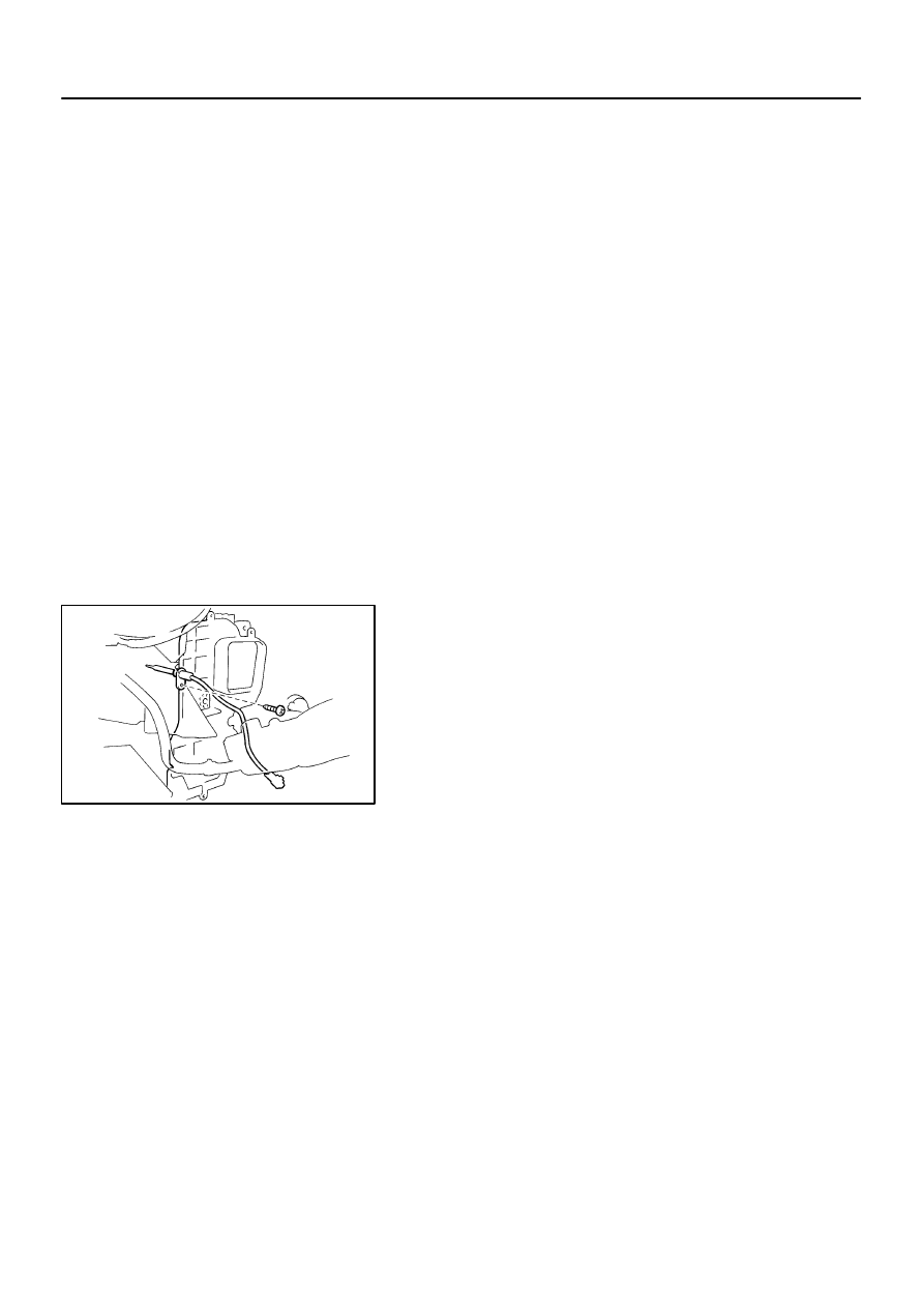
REMOVE EVAPORATOR TEMP. SENSOR

(a)

Disconnect the connector.

(b)

Remove the screw and pull out the sensor.

AC0BC–01

AIR CONDITIONING

EVAPORATOR TEMPERATURE SENSOR

AC–89

1646

1997 LEXUS ES300   (RM511U)

INSPECTION

INSPECT EVAPORATOR TEMP. SENSOR CIRCUIT
(See page 

DI–543

)

AC0BD–01

AC–90

AIR CONDITIONING

EVAPORATOR TEMPERATURE SENSOR

1647

1997 LEXUS ES300   (RM511U)

INSTALLATION

Installation is in the reverse order of removal (See page 

AC–88

).

N20291

AC0BH–01

Z13470

Magnetic Clutch Control

Low Pressure Side

ON (Continuity)

196 kpa

(2.0 kgf·cm

2

, 28 psi)

OFF (No Continuity)

High Pressure Side

3,140 kpa

(32.0 kgf·cm

2

, 455 psi)

OFF (No Continuity)

Z13471

Cooling Fan Control

ON

1,520 kpa

(15.5 kgf·cm

2

, 220 psi)

(No Continuity)

(Continuity)

OFF

1,226 kpa

(12.5 kgf·cm

2

, 178 psi)

AIR CONDITIONING

PRESSURE SWITCH

AC–91

1648

1997 LEXUS ES300   (RM511U)

PRESSURE SWITCH

ON–VEHICLE INSPECTION

1.

SET ON MANIFOLD GAUGE SET
(See page 

AC–17

)

2.

DISCONNECT CONNECTOR FROM PRESSURE
SWITCH

3.

RUN ENGINE AT APPROX. 1,500 RPM

4.

Magnetic Clutch Control:
INSPECT PRESSURE SWITCH OPERATION

(a)

Connect the positive (+) lead from the ohmmeter to termi-
nal 4 and the negative (–) lead to terminal 1.

(b)

Check continuity between terminals when refrigerant
pressure is changed, as shown in the illustration.

If operation is not as specified, replace the pressure switch.

5.

Cooling Fan Control:
INSPECT PRESSURE SWITCH OPERATION

(a)

Connect the positive (+) lead from the ohmmeter to termi-
nal 2 and the negative (–) lead to terminal 3.

(b)

Check continuity between terminals when refrigerant
pressure is changed, as shown in the illustration.

If operation is not as specified, replace the pressure switch.
6.

STOP ENGINE AND SET OFF MANIFOLD GAUGE SET

7.

CONNECT CONNECTOR TO PRESSURE SWITCH


Content   ..  49  50  51  52   ..