Lexus LS400 (2000 year). Manual - part 61
 

  Index      Lexus     Lexus LS400 (RM717U) - service repair manual 2000 year


Search            


Content   ..  59  60  61  62   ..


Lexus LS400 (2000 year). Manual - part 61


Z08747

Wire Harness Side

Z07390

Wire Harness Side

I03445

BE–72

BODY ELECTRICAL

INTERIOR LIGHT SYSTEM

1935

11.

Rear room light:
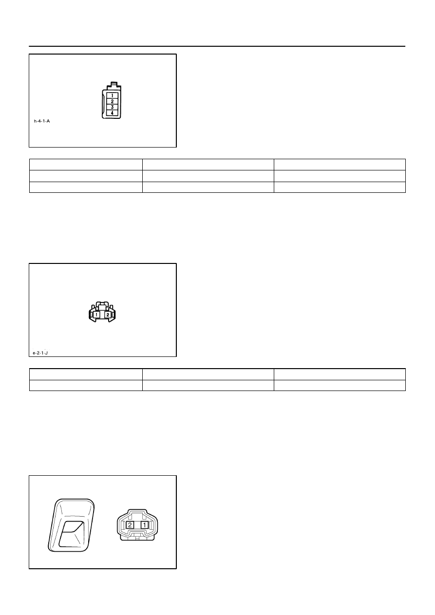
INSPECT REAR PERSONAL LIGHT ASSEMBLY CIR-
CUIT

Disconnect the connector from the light and inspect the con-
nector on the wire harness side, as shown.
If circuit is not as specified, inspect the power source or wire
harness.

Terminal connection

Condition

Specified condition

2 – Ground

Constant

Continuity

1 – Ground

Constant

Battery positive voltage

12.

Rear door courtesy light:
INSPECT REAR PERSONAL LIGHT ASSEMBLY CIR-
CUIT

Disconnect the connector from the light and inspect the con-
nector on the wire harness, as shown.
If circuit is not as specified, inspect the power source or wire
harness.

Terminal connection

Condition

Specified condition

1 – Ground

Constant

Battery positive voltage

13.

INSPECT SPOT LIGHT CONTINUITY

Using the ohmmeter, check that there is continuity between ter-
minals.
If continuity is not as specified, replace the bulb or spot light as-
sembly.

Z07390

Wire Harness Side

Z14894

ON

OFF

Z14895

Wire Harness Side

BODY ELECTRICAL

INTERIOR LIGHT SYSTEM

BE–73

1936

14.

INSPECT SPOT LIGHT CIRCUIT

Disconnect the connector from the light and inspect the con-
nector on the wire harness, as shown.
If circuit is not as specified, inspect the power source or wire
harness.

Terminal connection

Condition

Specified condition

1 – Ground

Constant

Battery positive voltage

15.

INSPECT VANITY LIGHT SWITCH CONTINUITY

Switch position

Tester connection

Specified condition

OFF (Closed)

No continuity

ON (Opened)

1 – 2

Continuity

If continuity is not as specified, replace the bulb or vanity light.

16.

INSPECT VANITY LIGHT SWITCH CIRCUIT

Disconnect the connector from the switch and inspect the con-
nector on the wire harness side, as shown.
If circuit is not as specified, inspect the power source or wire
harness.

Tester connection

Condition

Specified condition

2 – Ground

Constant

Continuity

1 – Ground

Constant

Battery positive voltage

Z14896

ON

I04052

1

2

BE–74

BODY ELECTRICAL

INTERIOR LIGHT SYSTEM

1937

17.

INSPECT LUGGAGE COMPARTMENT DOOR COUR-
TESY SWITCH CONTINUITY

Switch position

Tester connection

Specified condition

OFF (Closed)

No continuity

ON (Opened)

1 – Switch body

Continuity

If operation is not as specified, replace the switch.

18.

INSPECT DOOR COURTESY LIGHT CONTINUITY

Using the ohmmeter, check that there is continuity between ter-
minals.
If continuity is not as specified, replace the light assembly or
bulb.

BE0BT–01

I03231

Instrument Panel Junction Block


 STOP Fuse


 GAUGE Fuse

Stop Light Switch

High Mount Stop Light

Rear Combination Light

Rear Light Assembly

Light Failure Sensor

BODY ELECTRICAL

STOP LIGHT SYSTEM

BE–75

1938

STOP LIGHT SYSTEM

LOCATION


Content   ..  59  60  61  62   ..