Lexus LS400 (2000 year). Manual - part 62
 

  Index      Lexus     Lexus LS400 (RM717U) - service repair manual 2000 year


Search            


Content   ..  60  61  62  63   ..


Lexus LS400 (2000 year). Manual - part 62


BE0BU–01

Z08737

Z08738

Wire Harness Side

I03418

Wire Harness Side

e–16–1–A

BE–76

BODY ELECTRICAL

STOP LIGHT SYSTEM

1939

INSPECTION

1.

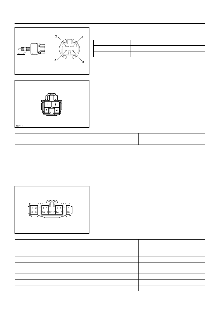
INSPECT STOP LIGHT SWITCH CONTINUITY

Switch position

Tester connection

Specified condition

Switch pin free

1 – 2

Continuity

Switch pin pushed in

3 – 4

Continuity

If continuity is not as specified, replace the switch.

2.

INSPECT STOP LIGHT SWITCH CIRCUIT

Disconnect the connector from the switch and inspect the con-
nector on the wire harness side, as shown.

Tester connection

Condition

Specified condition

2 – Ground

Constant

Battery positive voltage

If circuit is not as specified, inspect the power source or wire
harness.

3.

INSPECT LIGHT FAILURE SENSOR CIRCUIT

Disconnect the connector from the sensor and inspect the con-
nector on the wire harness side, as shown.

Tester connection

Condition

Specified condition

2 – Ground

Constant

* Continuity

3 – Ground

Constant

* Continuity

4 – Ground

Constant

* Continuity

6 – Ground

Constant

* Continuity

7 – Ground

Constant

* Continuity

11 – Ground

Constant

Continuity

16 – Ground

Constant

* Continuity

1 – Ground

Stop light switch position OFF

No voltage

BODY ELECTRICAL

STOP LIGHT SYSTEM

BE–77

1940

1 – Ground

Stop light switch position ON

Battery positive voltage

8 – Ground

Stop light switch position OFF

No voltage

8 – Ground

Stop light switch position ON

Battery positive voltage

9 – Ground

Ignition switch position LOCK or ACC

No voltage

9 – Ground

Ignition switch position ON

Battery positive voltage

14 – Ground

Ignition switch position LOCK or ACC

No voltage

14 – Ground

Ignition switch position ON

Battery positive voltage

16 – Ground

Light control switch position OFF

No voltage

16 – Ground

Light control switch position TAIL or HEAD

Battery positive voltage

*: There is resistance because this circuit is grounded through
the bulb.
If circuit is as specified, try replacing the sensor with a new one.
If the circuit is not as specified, inspect the circuits connected
to other parts.

BE0BV–01

I03232

Instrument Panel Junction Block


 WIPER Fuse

Washer Tank

Headlight Cleaner
Relay

Headlight Cleaner Motor

Ignition Switch

Light Control Switch

Headlight Cleaner Switch

BE–78

BODY ELECTRICAL

HEADLIGHT CLEANER SYSTEM

1941

HEADLIGHT CLEANER SYSTEM

LOCATION

BE0BW–03

N13311

ON

Z08751

Wire Harness Side

N01058

1

2

3

4

5

Z05676

Wire Harness Side

BODY ELECTRICAL

HEADLIGHT CLEANER SYSTEM

BE–79

1942

INSPECTION

1.

INSPECT HEADLIGHT CLEANER SWITCH CONTINU-
ITY

Condition

Tester connection

Specified condition

Switch OFF

No continuity

Switch ON

4 – 5

Continuity

Illumination circuit

1 – 6

Continuity

If continuity is not as specified, replace the switch.

2.

INSPECT HEADLIGHT CLEANER SWITCH CIRCUIT

Disconnect the switch connector and inspect the connector on
wire harness side, as shown.
If circuit is not as specified, inspect the circuits connected to oth-
er parts.

Tester connection

Condition

Specified condition

5 – Ground

Headlight Light OFF

No continuity

5 – Ground

Headlight Light ON

Continuity

4 – Ground

Ignition switch position LOCK or ACC

No voltage

4 – Ground

Ignition switch position ON

Battery positive voltage

6 – Ground

Headlight or taillight Light ON

Battery positive voltage

3.

INSPECT HEADLIGHT CLEANER RELAY OPERATION

(a)

Check that there is no continuity between terminals 2 and
5.

(b)

Connect the positive (+) lead from the battery to terminals
1 and 5, and the negative (–) lead to terminal 3.

(c)

Connect the negative (–) lead from the battery to terminal
4, and check that there is continuity between terminals 2
and 5 for 0.4 – 0.6 seconds, then there is no continuity.

If operation is not as specified, replace the relay.

4.

INSPECT HEADLIGHT CLEANER RELAY CIRCUIT

Disconnect the connector from the relay and inspect the con-
nector on wire harness side, as shown.


Content   ..  60  61  62  63   ..