Index Land Rover LT230Q TRANSFER BOX - service manual 1997 year
Search
Content .. 1 2 3 4 ..
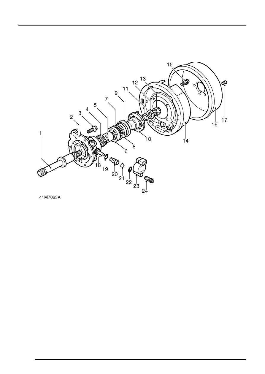
LT230Q TRANSFER BOX. Manual - part 3
TRANSFER BOX
8
DESCRIPTION AND OPERATION