Land Rover V8 engine. Manual - part 10


  Index      Land Rover     Land Rover V8 engine (3.5, 3.9, 4.2 Litre) - service repair 1996 year


Search            


Content   ..  8  9  10  11   ..


Land Rover V8 engine. Manual - part 10


ENGINE

26

OVERHAUL

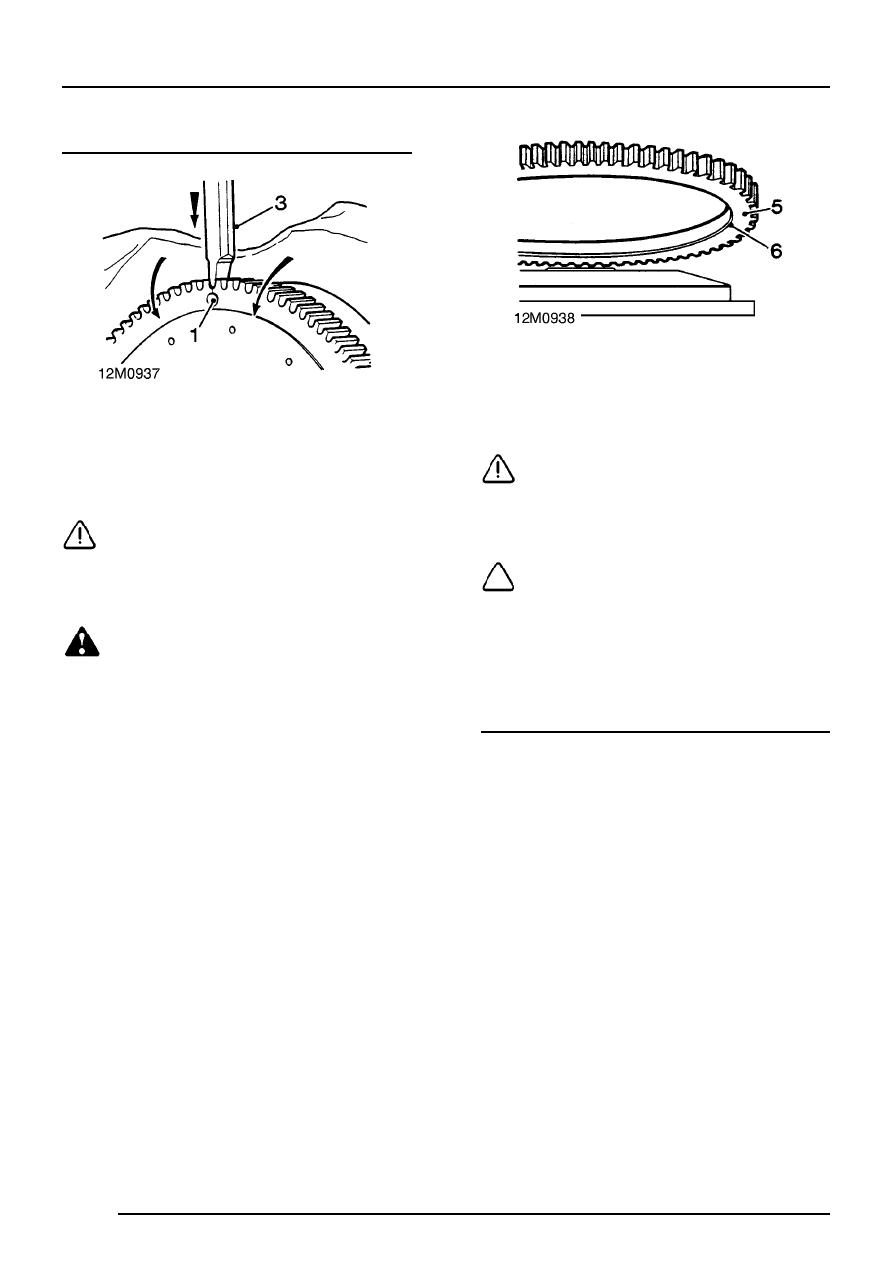
Flywheel ring gear - renew

1. Drill a 10 mm diameter hole axially at base of

tooth and inner diameter of starter ring,
sufficiently deep enough to weaken ring gear.

CAUTION: Do not allow drill to enter
flywheel.

2. Secure flywheel in soft jawed vice.
3. Split ring gear using a cold chisel.

WARNING: Wear safety goggles and take
precautions against flying fragments when
splitting ring gear.

4. Remove flywheel from vice, remove old ring

gear, and place flywheel, clutch side down, on
a flat surface.

5. Heat new ring gear uniformly to between

170

°

and 175

°

C.

CAUTION: Do not exceed this
temperature.

6. Locate ring gear on flywheel with chamfered

inner diameter towards flywheel flange.

NOTE: If ring gear is chamfered on both
sides, it can be fitted either way round.

7. Press ring gear onto flywheel until it butts

against flywheel flange.

8. Allow flywheel to air cool.

Flywheel - refit

1. Fit flywheel and locate on 2 dowels.
2. Fit flywheel bolts.
3. With assistance, restrain crankshaft and

tighten flywheel bolts to correct torque.

ENGINE

OVERHAUL

27

DRIVE PLATE AND RING GEAR ASSEMBLY

Drive plate and ring gear assembly - remove

1. Mark each component to enable reassembly in

original position.

2. Remove 4 bolts securing drive plate.
3. Remove clamp ring, flexible drive plate, hub

aligner and ring gear assembly.

4. Remove 6 socket head screws securing

crankshaft adapter plate, remove adapter plate
and selective shim.

Inspect

1. Inspect flexible drive plate for cracks and

distortion.

2. Renew drive plate if necessary.
3. Inspect ring gear for worn, chipped and broken

teeth.

4. Renew ring gear assembly if necessary.

Drive plate and ring gear assembly - refit

CAUTION: To prevent distortion to flexible
drive plate when bolted to torque
converter, drive plate setting height must

be checked as follows:

1. Fit existing shim and crankshaft adapter plate.
2. Fit socket head screws and lightly tighten.
3. Fit ring gear assembly, hub aligner, drive plate

and clamping ring, fit bolts and lightly tighten.

4. Check the setting height.

Drive plate setting height = 8.08 to 8.20 mm.

5. Remove bolts, remove clamp ring, flexible

drive plate, hub aligner and ring gear
assembly.

6. Remove socket head screws, remove

crankshaft adapter and shim.

ENGINE

28

OVERHAUL

7. Measure existing shim and, if necessary, select

appropriate shim to maintain setting height.
Shims available:
1.20 - 1.25mm
1.30 - 1.35mm
1.40 - 1.45mm
1.50 - 1.55mm
1.60 - 1.65mm
1.70 - 1.75mm
1.80 - 1.85mm
1.90 - 1.95mm
2.00 - 2.05mm
2.10 - 2.15mm

8. Fit shim selected, position adapter, ensuring

marks previously made line up, fit socket head
bolts and tighten to correct torque.

9. Fit ring gear assembly, hub aligner, flexible

drive plate and clamp ring. ensuring marks
previously made line up.

10. Apply Loctite 242 to threads of bolts, fit bolts

and tighten to correct torque.

CRANKSHAFT, MAIN AND BIG-END BEARINGS

Crankshaft end - float - check

1. Set-up DTI to measure end float.
2. Move crankshaft forwards and zero gauge.
3. Move crankshaft rearwards, record end-float

reading obtained.
Crankshaft end-float = 0.10 to 0.20mm.

4. Remove DTI.

NOTE: Crankshaft end-float is controlled
by thrust faces on upper half of centre
main bearing shell.

Big-end bearings - remove

1. Remove sump.

2. Remove 2 bolts securing oil strainer.
3. Remove strainer, remove and discard gasket.
4. Suitably identify bearing caps to their

respective connecting rods.

5. Remove 2 nuts securing each bearing cap.
6. Remove bearing cap and bearing shell.

CAUTION: Keep bearing caps and shells
in their fitted order.

7. Fit a length of plastic tubing over each

connecting rod bolt.

8. Push each piston up its respective bore and

remove shells from connecting rods.

CAUTION: Keep bearing shells in their
fitted order.

ENGINE

OVERHAUL

29

Big-end bearings - Inspection

1. Check big-end bearing shells for wear and

damage.

2. Renew big-end bearing shells as necessary.

NOTE: Big-end bearings are available in
0.254 mm and 0.508 mm undersizes.

Big-end bearings - refit

1. Fit bearing shells to each connecting rod.
2. Lubricate bearing shells and crankshaft

journals with clean engine oil.

3. Pull connecting rods onto crankshaft journals

and remove plastic tubing.

4. Fit bearing shells to each big-end bearing cap.

5. Lubricate bearing shells and fit bearing caps

ensuring reference marks on connecting rods
and bearing caps are aligned.

NOTE: Rib on edge of bearing cap must
face towards front of engine on RH bank
of cylinders and towards rear on LH bank

of cylinders.

6. Fit bearing cap nuts and tighten to correct

torque.

7. Check connecting rods move freely sideways

on crankshaft. Tightness indicates insufficient
bearing clearance or misaligned connecting
rod.

8. Check clearance between connecting rods on

each crankshaft journal.
Connecting rod clearance = 0.15 to 0.37 mm.

9. Clean oil strainer.

10. Clean gasket mating faces on strainer and

cylinder block.

11. Fit gasket to strainer, position strainer, fit bolts

and tighten to correct torque.

12. Fit sump.


Content   ..  8  9  10  11   ..