Land Rover V8 engine. Manual - part 9
ENGINE
22
OVERHAUL
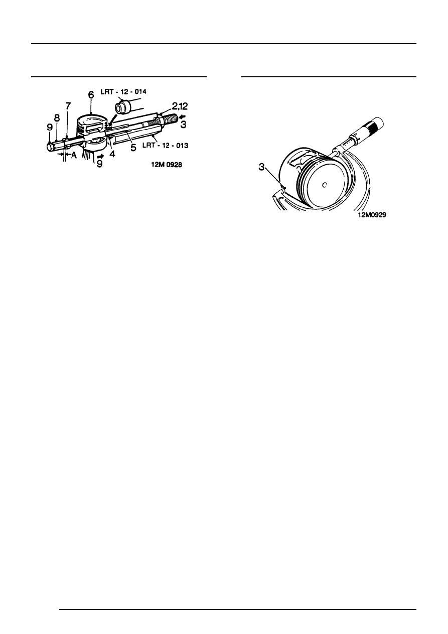
Pistons - remove
1. Clamp hexagon body of LRT-12-013 in vice.
2. Screw large nut back until flush with end of
centre screw.
3. Push centre screw forward until nut contacts
thrust race.
4. Locate piston adapter LRT-12-014 with its long
spigot inside bore of hexagon body.
5. Fit parallel sleeve, grooved end first, onto
centre screw and smear outside diameter with
engine oil.
6. Locate piston and connecting rod assembly on
centre screw and up to adapter LRT-12-014.
7. Fit remover/replacer bush of LRT-12-014 on
centre screw with flanged end away from
gudgeon pin.
8. Screw stop nut onto centre screw leaving
clearance A, between nut and
remover/replacer bush.
Clearance A = 3 mm.
9. Lock the stop nut securely with lockscrew.
10. Push connecting rod to right to locate end of
gudgeon pin in adapter LRT-12-014.
11. Ensure remover/replacer is located in gudgeon
pin bore of piston.
12. Screw large nut up to thrust race.
13. Hold lockscrew and turn large nut until
gudgeon pin is withdrawn from piston.
14. Dismantle tool and remove piston, connecting
rod and gudgeon pin.
15. Repeat above operation for remaining pistons.
Pistons - inspection
1. Clean carbon from pistons
2. Inspect pistons for distortion and cracks.
3. Measure piston diameter at 90
°
to gudgeon pin
axis and 8 mm from bottom of skirt. The piston
must be 0.018 mm to 0.033 mm smaller than
cylinder bore.