Land Rover V8 engine. Manual - part 8


  Index      Land Rover     Land Rover V8 engine (3.5, 3.9, 4.2 Litre) - service repair 1996 year


Search            


Content   ..  6  7  8  9   ..


Land Rover V8 engine. Manual - part 8


ENGINE

18

OVERHAUL

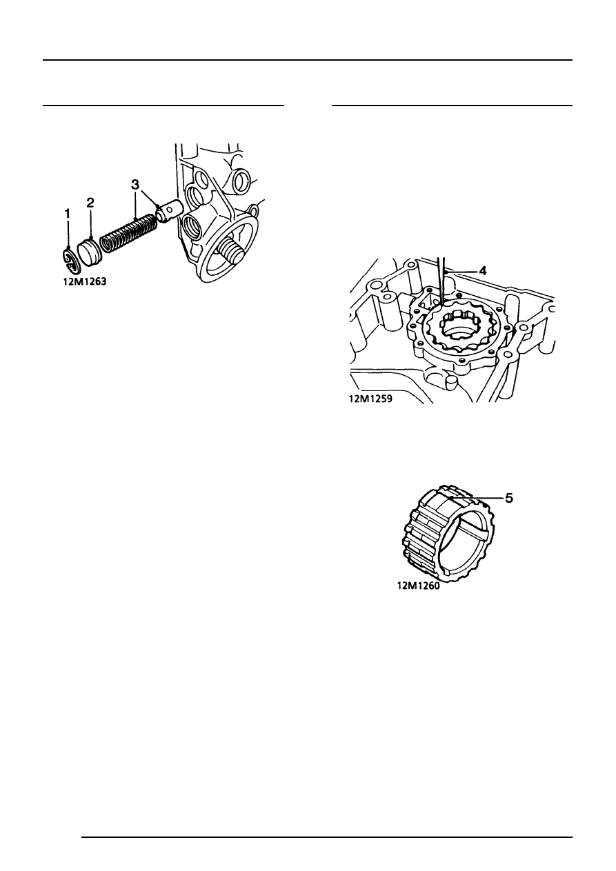
Oil pressure relief valve - remove

1. Remove circlip.
2. Remove relief valve plug, remove and discard

’O’ ring.

3. Remove relief valve spring and piston.

Oil pump - inspection

1. Thoroughly clean oil pump drive gear, cover

plate, rotors and housing. Remove all traces of
Loctite from cover plate securing screws;
ensure tapped holes in timing cover are clean
and free from oil.

2. Check mating surfaces of cover plate, rotors

and housing for scoring.

3. Assemble rotors and oil pump drive gear in

housing ensuring that reference marks are
aligned.

4. Using feeler gauges, check clearance between

teeth of inner and outer rotors:
Maximum clearance = 0.25 mm

5. Remove oil pump drive gear, check depth of

any wear steps on gear teeth:
Wear step maximum depth = 0.15 mm

ENGINE

OVERHAUL

19

6. Place a straight edge across housing.
7. Using feeler gauges, check clearance between

straight edge and rotors:
Maximum clearance = 0.1 mm

Oil pressure relief valve - inspection

1. Clean relief valve components and piston bore

in timing cover.

2. Check piston and bore for scoring and that

piston slides freely in bore with no perceptible
side movement.

3. Check relief valve spring for damage and

distortion; check spring free length:
Spring free length = 60.0 mm

Oil pump - refit

1. Lubricate rotors, oil pump drive gear, cover

plate and housing with engine oil.

2. Assemble rotors in housing ensuring that

reference marks are aligned.

3. Position cover plate to housing.
4. Apply Loctite 222 to threads of cover plate

screws, fit but do not fully tighten screws.

5. Position drive gear in oil pump, tighten cover

plate screws to correct torque.

6. Fit timing cover.

Oil pressure relief valve - refit

1. Lubricate new ’O’ ring with engine oil and fit to

relief valve plug.

2. Lubricate relief valve spring, piston and piston

bore with engine oil.

3. Assemble piston to relief valve spring, insert

piston and spring into piston bore.

4. Fit relief valve plug, depress plug and fit circlip.
5. Ensure circlip is fully seated in groove.

ENGINE

20

OVERHAUL

CAMSHAFT AND TAPPETS

Camshaft and tappets - remove

1. Remove rocker shaft assemblies.
2. Remove pushrods and store in fitted order.
3. Remove timing chain and gears.

4. Remove tappets and retain with their

respective pushrods.

NOTE: If tappets cannot be removed due
to damaged camshaft contact area,
proceed as follows:

5. Lift tappets in pairs to the point where

damaged face is about to enter tappet bore
and fit rubber bands to retain tappets. Repeat
until all tappets are retained clear of camshaft
lobes. The tappets can then be withdrawn out
the bottom of their bores when the sump is
removed.

6. Withdraw camshaft, taking care not to damage

bearings in cylinder block.

Camshaft and tappets - inspection

1. Throughly clean all components.
2. Inspect camshaft bearing journals and lobes

for signs of wear, pitting, scoring and
overheating.

3. Support camshaft front and rear bearings on

vee blocks, and using a DTI, measure
camshaft run-out on centre bearing.
Maximum permitted run-out = 0.05 mm.

4. Clean and inspect tappets. Check for an even,

circular wear pattern on the camshaft contact
area. If contact area is pitted or a square wear
pattern has developed, tappet must be
renewed.

5. Inspect tappet body for excessive wear or

scoring. Replace tappet if scoring or deep wear
patterns extend up to oil feed area. Clean and
inspect tappet bores in engine block.

6. Ensure that tappets rotate freely in their

respective bores.

7. Inspect pushrod contact area of tappet, replace

tappet if surface is rough or pitted.

ENGINE

OVERHAUL

21

Camshaft and tappets - refit

1. Lubricate camshaft journals with clean engine

oil and carefully insert camshaft into cylinder
block.

2. Immerse tappets in clean engine oil. Before

fitting, pump the inner sleeve of tappet several
times using a pushrod, to prime tappet and
reduce tappet noise when engine is first
started.

3. Lubricate tappet bores with clean engine oil

and fit tappets in removed order.

NOTE: Some tappet noise may be evident
on initial start-up. If necessary, run the
engine at 2500 rev/min for a few minutes

until noise ceases.

4. Fit timing chain and gears.
5. Fit rocker shaft assemblies.

PISTONS, CONNECTING RODS, PISTON RINGS
AND CYLINDER BORES

Pistons and connecting rods - remove

1. Remove cylinder head(s).
2. Remove big-end bearings.
3. Remove carbon ridge from top of each cylinder

bore.

4. Suitably identify each piston to its respective

cylinder bore.

5. Push connecting rod and piston assembly to

top of cylinder bore and withdraw assembly.

6. Remove plastic tubing from connecting rod

bolts.

7. Repeat above procedure for remaining pistons.

Piston rings - remove

1. Using a suitable piston ring expander, remove

piston rings.

2. Remove carbon from piston ring grooves.

NOTE: Use an old broken piston ring with
a squared off end.

CAUTION: Do not use a wire brush.

Piston rings - inspection

1. Temporarily fit new compression rings to

piston.

NOTE: The ring marked ’TOP’ must be
fitted, with marking uppermost, into
second groove. The chrome ring fits into

top groove and can be fitted either way round.

2. Check compression ring to groove clearance:

Top compression ring = 0.05 to 0.10 mm.
2nd compression ring = 0.05 to 0.10 mm.

3. Insert new piston ring into relevant cylinder,

held square to bore with piston, and check ring
gaps.
Top compression ring = 0.44 to 0.57 mm.
2nd compression ring = 0.44 to 0.57 mm.
Oil control ring rails = 0.38 to 1.40 mm.

4. Use a fine-cut flat file to increase gap if

required. Select a new piston ring if gap
exceeds limit.


Content   ..  6  7  8  9   ..