Range Rover Classic. Manual - part 145
CHASSIS AND BODY
3
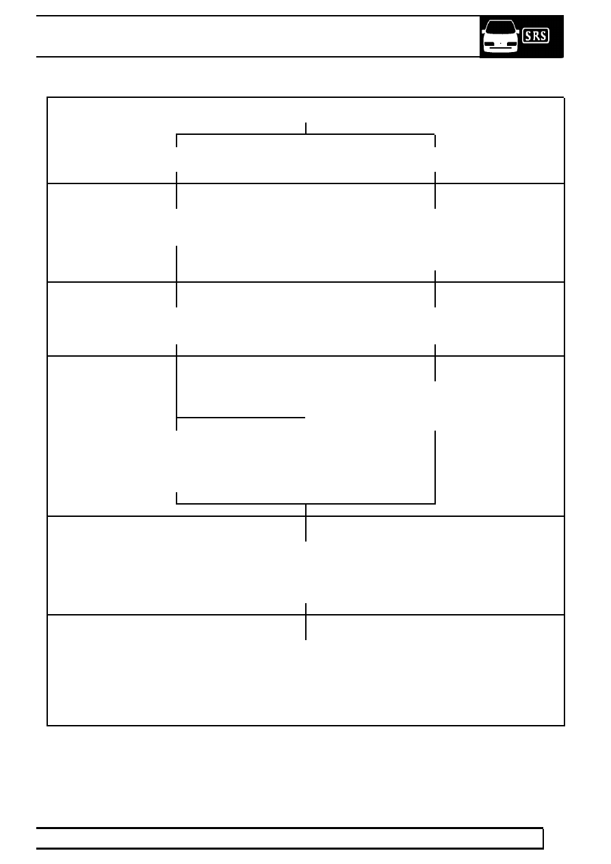
REPAIR
SUBSTRATE
ALUMINIUM PANELS
PANEL REPAIR
REPLACEMENT PANEL
PREPARATION
Wet for using P60 Grade paper or dry sand using
P240 grit discs.
Wet flat using P60 Grade paper or dry sand using
P240 grit discs.
Care must be taken to avoid cutting through to bare
aluminium.
BODY FILLING
If filling is required, thoroughly abrade bare aluminium
area to be filled and apply Standox Polyester
If filling is required, fill small indentations with Standox
Polyster stopper 430-5029.
ETCHING
This process is not required if the original electrocoat
primer is in sound condition.
IF NOT
Etch the bare aluminium and filler with auto-speed self
etch primer 414-1171, mixed 1:1 with activator
801-7995. Apply one coat and allow to dry for
approximately 20 minutes. Recoat within 1 hour.
PRIMING
To obtain maximum adhesion and excellent build, apply
Standox 2K 4:1 full primer 405-0381. Coats of 30-40 microns
can be wet flatted with P60 grade paper after 45 minutes at
20
°
C.
COLOUR COATING
Apply either Standox 2K Standocryl or Standox Metallic
Basislack to the colour required. Hardeners and thinners will
vary depending upon system employed, conditions available,
temperature and size of vehicle etc. Refer to paint
manufacturer’s Technical Information Sheet for correct
selection.