Range Rover Classic. Manual - part 64


  Index      Land Rover     Range Rover Classic - service manual 1995 year


Search            


Content   ..  62  63  64  65   ..


Range Rover Classic. Manual - part 64


41

TRANSFER GEARBOX

4

DESCRIPTION AND OPERATION

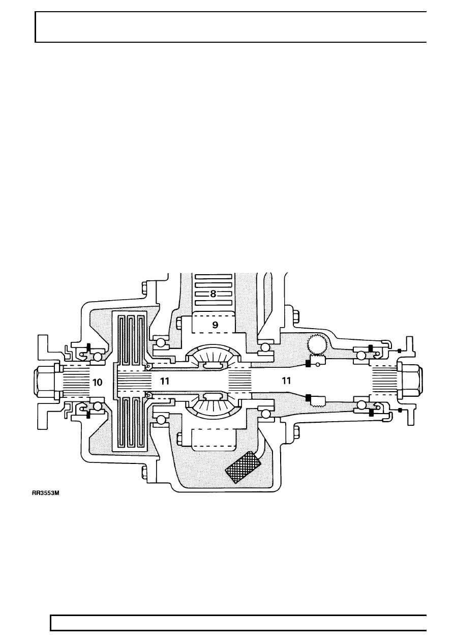
Differential and viscous coupling

The Morse chain 8 drives a conventional type
differential 9. The front and rear output shafts 10 and
11 are splined to the differential output pinions. The
front output shaft 10 forms the outer member of the
viscous coupling, while the inner member plates are
splined to the rear output shaft 11.

Its only function is to limit the maximum difference in
speed between the two shafts, with the effect of
automatically locking the differential.

The maximum difference in speed permitted by the
viscous coupling must however be sufficient to allow
the vehicle to be driven on a dry road surface, in a
circle on full lock, without inducing ’wind up’ or
causing damage to the transmission.

The viscous coupling has alternate plates splined to
the inner and outer members.

One set of plates is splined to 10, the outer
member/front shaft and the other plates are splined
the rear output shaft 11. The coupling is filled with a
special silicone jelly which allows sufficient slip to
occur in normal driving conditions but, which increase
the drag between the plates as the speed difference
and temperature rises, thus eliminating the need for a
manual differential lock.

BORG WARNER

1

FAULT DIAGNOSIS

BORG WARNER - SYMPTOMS

Oil leaks

1. Check that nylon ventilation pipes are not

blocked or damaged.

2. Check lubrication level and specification in both

boxes and recheck leaks.

3. Location area of leak.

A -

Transfer box front output flange oil seal.

B -

Transfer box rear output flange oil seal.

C -

Oil leaking from vent hole between main
and transfer boxes.
The oil may be leaking from the main or
transfer box oil seals. Renew the faulty
seal.

D -

Oil leaking from engine flywheel housing.
The oil may be leaking from the gearbox
front seal, torque converter seal or the
engine crankshaft rear seal. Renew the
faulty seal.

Loss of drive - no abnormal noise from box.

1. Check that the main transmission unit is

satisfactory and confirm that loss of drive is in
the transfer box.

2. Check by ’feel’ the operation of the High/Low

transfer gear selection. Suspect failed viscous
unit.

Knocking or rattling noise in high and low ratio.

1. Check lubricant specification and level, if low do

not top up at this stage.

2. Drain lubricant and check for contamination or

metal particles.
Suspect drive chain has stretched.

Abnormal noise in operation.

1. Check lubricant specification and level, if low do

not top up at this stage.

2. Drain lubricant and check for contamination or

metal particles.
Suspect oil pump failure, mechanical wear or
damage.

Transmission wind up

’Transmission wind up’ is a build up of tension in the
transmission which will only occur if either the
differential or viscous unit is partially or completely
seized.

Vibration - harshness

1. Check operation of differential and viscous units.

Ensure that neither is partially seized.

NOTE: If both are satisfactory, but the
vibration - harshness is still present, the
alignment of the propeller shafts and

balance of the road wheels should be checked.

For balancing of road wheels.

See WHEELS AND

TYRES, Repair, Wheel Balancing

For propeller shaft alignment.

See PROPELLER

SHAFTS, Description and operation, Propeller
Shaft Alignment

BORG WARNER

1

REPAIR

REAR OUTPUT SHAFT OIL SEAL

Service tool: 18G1422

1. Disconnect rear propeller shaft from output drive

flange and tie shaft to one side.

2. Apply parkbrake and release drive flange nut.
3. Release parkbrake and remove brake drum

secured with two screws.

4. Remove output shaft nut, steel washer, rubber

seal and withdraw flange.

5. Tap dust cover from housing and remove oil

seal.

6. Lubricate and fit new seal using service tool

18G1422. Fit so spring side of seal abuting
circlip.

7. Fit dust cover.
8. If necessary release circlip from drive flange to

allow new bolts to be installed.

9. Examine flange, if surface is corroded or a

groove worn by previous seal discard flange.

10. Lubricate running surface and fit flange. Do not

tighten nut.

11. Fit brake drum and secure with two screws.

Apply parkbrake and tighten drive flange nut to
224 Nm

12. Fit propeller shaft. Tighten to

46Nm

FRONT OUTPUT SHAFT OIL SEAL

Service tool: 18G1422

1. Disconnect front propeller shaft from flange.
2. Apply parkbrake and release drive flange nut.
3. Remove output shaft nut, steel washer, rubber

seal and withdraw flange.

4. Prise out oil seal.
5. Lubricate and fit new seal using service tool

18G1422. Fit spring side of seal abuting circlip.

6. Examine flange if surface is corroded or worn by

previous seal discard flange.

7. Lubricate seal running surface of flange.
8. Fit flange. Tighten to

224 Nm

9. Refit propeller shaft. Tighten to

46Nm

41

TRANSFER GEARBOX

2

REPAIR

BORG WARNER TRANSFER GEARBOX

Service repair no - 41.20.25

Remove

1. Site vehicle on ramp and chock wheels.
2. Disconnect battery negative lead.
3. Remove fan blade assembly.

NOTE: The nut securing viscous unit has
left hand thread.

4. Disconnect airflow meter to plenum chamber

hose. (V8i only)

5. Remove two gear lever knobs. If Automatic type

remove gear selector.

See ELECTRICAL,

Repair, Automatic Gear Selector-Panel Bulb

6. Remove floor mounted console assembly.

See

CHASSIS AND BODY, Repair, Centre
Console

7. Remove padding from top of transmission

tunnel.

8. Loosen pinch bolt and remove upper gear lever.
9. Remove screws and detach high low lever and

main gearlever retaining plates.

Underneath vehicle

10. Drain oil from transfer gearbox.
11. Refit plug.

12. Disconnect Lambda sensor. (V8i only)
13. Remove front exhaust sections. (V8i only)
14. Remove chassis cross member secured by eight

nuts and bolts. (V8i only)

15. Mark each drive flange for reassembly and

disconnect front and rear propeller shafts from
transfer box. Tie the shafts to one side.

16. Disconnect the speed transducer multiplug.
17. Remove transmission brake drum. Remove four

bolts securing back plate to transfer box and tie
assembly aside complete with handbrake cable.

18. Remove two bolts and withdraw clutch slave

cylinder from bell housing. (Manual only)


Content   ..  62  63  64  65   ..