Range Rover. Manual - part 330


  Index      Land Rover     Range Rover P38 - service manual 1995 year


Search            


Content   ..  328  329  330  331   ..


Range Rover. Manual - part 330


NAVIGATION SYSTEM

1

DESCRIPTION AND OPERATION

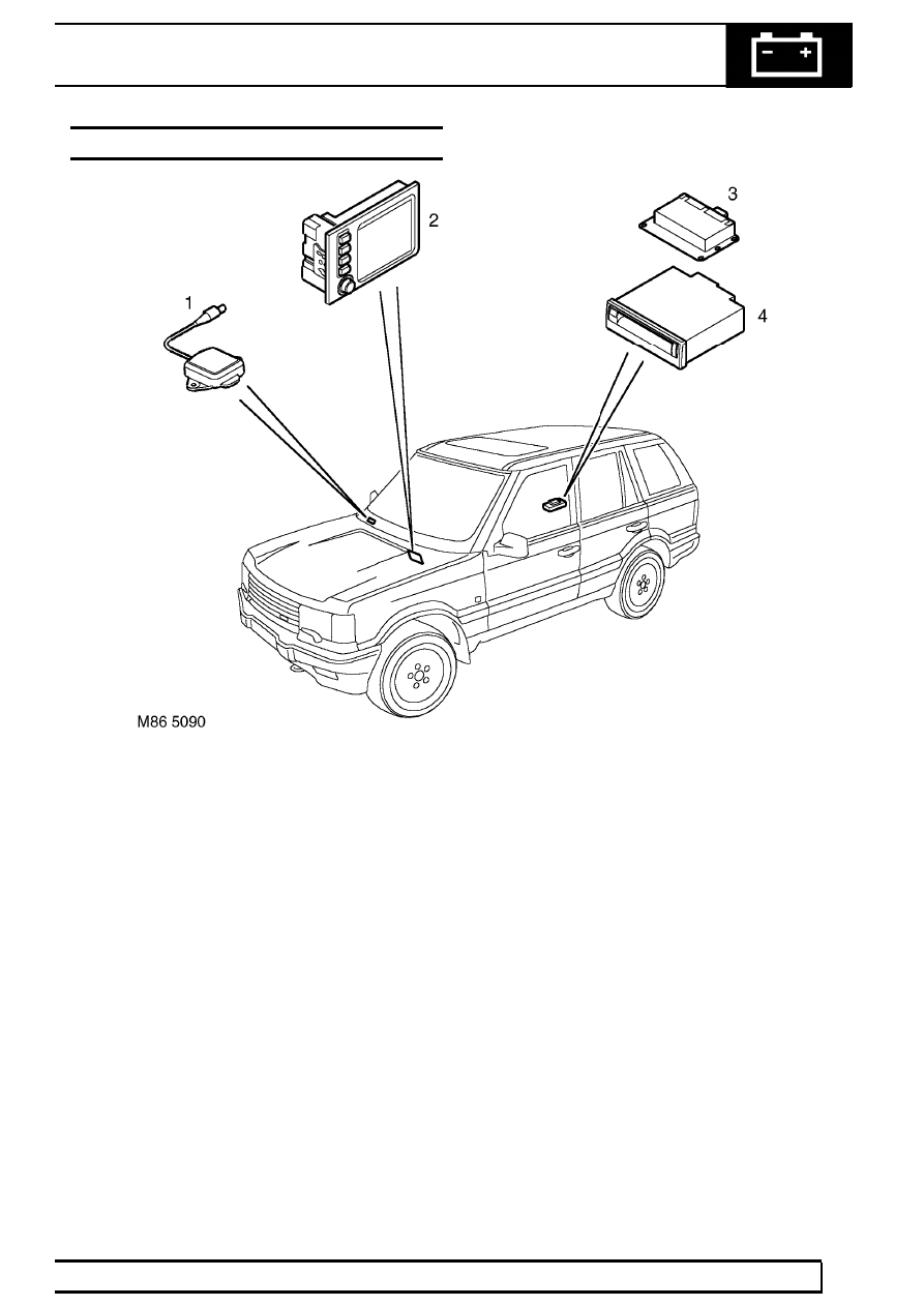
NAVIGATION SYSTEM COMPONENT LAYOUT

1. GPS antenna
2. Navigation display unit
3. GPS receiver
4. Navigation computer

87

NAVIGATION SYSTEM

NEW RANGE ROVER

2

DESCRIPTION AND OPERATION

NAVIGATION SYSTEM CONTROL DIAGRAM

A=Hardwired connections; B=K Bus; F=RF Transmission; K=I Bus

NAVIGATION SYSTEM

3

DESCRIPTION AND OPERATION

1. Antenna Amplifier LH
2. Antenna Amplifier RH
3. Headunit
4. DSP Amplifier
5. Speakers
6. Navigation display unit
7. BeCM
8. GPS receiver
9. GPS antenna

10. Diagnostic socket
11. Navigation computer
12. CD Autochanger

87

NAVIGATION SYSTEM

NEW RANGE ROVER

4

DESCRIPTION AND OPERATION

DESCRIPTION

General

Each navigation system provides computer generated
audible and visual route guidance information to
enable the driver to reach a desired destination. The
system allows the driver to choose the desired route
using minor or major roads or motorways and the
quickest or shortest route. Directions to hospitals,
museums, monuments and hotels are also available.
The computer uses map information stored on a
CD-ROM to determine the best route for the journey
and provide the driver with details of directions and
approaching junctions.

The current position of the vehicle is determined using
a Global Positioning System (GPS). The GPS uses
satellites which orbit the earth every 12 hours at a
height of 12500 miles (20000 km) and transmit radio
signals to provide information about the satellite
position i.e. latitude, longitude, altitude, almanac data
and time.

The almanac data is the current status of the 24
satellites which orbit the earth. The computer
determines which satellites are ’visible’ to the system
and their current position and relationship to each
other. Using this information the computer can
account for positional deviations of the satellites and
compensate to enhance the accuracy of the
navigation system. The navigation system requires
the almanac data from at least four different satellites
to calculate a three dimensional ’fix’ on its location. As
the vehicle moves the computer continually up dates
this information so that at all times the computer
knows the precise location of the vehicle.

The direction of the vehicle is determined by the
navigation computer using a solid state gyro sensor
located inside the computer. The gyro sensor supplies
angular acceleration data for the vehicle to the
navigation computer. The computer uses this
information to determine the direction of travel of the
vehicle.

NAVIGATION SYSTEM COMPONENTS

The following components make up the navigation
system:

Navigation computer

GPS receiver

GPS antenna

Navigation display unit

Navigation Computer

The navigation computer is located in the right hand
side of the luggage compartment, attached to a
bracket. The computer is the main component in the
navigation system and receives inputs from the BeCM
and the GPS receiver. The navigation computer
contains a solid state piezo gyro which measures the
motion of the vehicle around its vertical axis. The gyro
operates on the principle known as the Coriolis force.
The Coriolis force is the force that appears to
accelerate a body moving away from its rotational axis
against the direction of rotation of the axis. Refer to
Operation in this section for detailed operation.

Using the inputs from the BeCM, the GPS receiver
and the gyro sensor, the computer can determine the
vehicle’s current position, direction and speed.

The navigation computer also houses the CD-ROM
drive. The drive is used to read map data from country
specific CD’s and also to load updated software into
the computer. A button, located adjacent to the CD
slot, is provided to eject the CD from the unit. If
ignition is on, one press of the button will eject the CD.
If the ignition is off, two presses are required, one to
wake up the system and the second to eject the CD.

The D&C unit is connected with a 12-way MQL
connector and a 6 way AMP connector.


Content   ..  328  329  330  331   ..