Range Rover. Manual - part 222


  Index      Land Rover     Range Rover P38 - service manual 1995 year


Search            


Content   ..  220  221  222  223   ..


Range Rover. Manual - part 222


SUPPLEMENTARY RESTRAINT SYSTEM

5

REPAIR

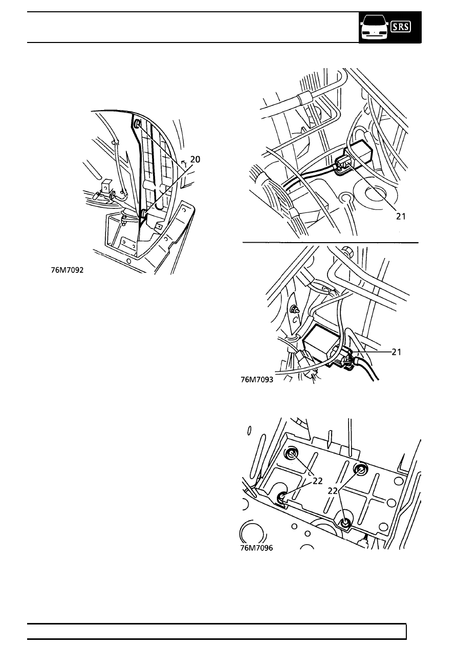
20. Remove 2 trim studs securing air cleaner baffle

beneath LH wheel arch. Remove baffle.

21. Disconnect both SRS crash sensor multiplugs.

22. Remove 4 bolts securing battery tray.

75

SUPPLEMENTARY RESTRAINT SYSTEM

NEW RANGE ROVER

6

REPAIR

23. Remove 2 bolts securing air cleaner to valance.

24. Raise air cleaner and battery tray to gain access

to crash sensor harness clips.

25. Release clips securing each crash sensor

harness to valance.

26. Release harness grommets. Feed both

harnesses through valance into wheel arches.

27. Release 3 clips securing each crash sensor

harness to underside of wheel arches.

28. Release harness bulkhead grommets. Feed

harnesses through bulkhead into passenger
compartment.

29. Disconnect SRS multiplug from instrument pack.

SUPPLEMENTARY RESTRAINT SYSTEM

7

REPAIR

30. Disconnect driver’s air bag module connector.

Release connector and harness from clips.

31. Release 13 clips securing SRS harness to fascia

frame.

NOTE: Due to restricted access, two outer
clips ’A’ securing harness above heater
unit may have to be cut. Ensure that

location holes are clear. Collect loose ends of
clips.

32. Release 3 clips securing fascia harness trunking

to passenger side fascia frame.

33. Remove nut securing lower end of each blower

assembly to fascia frame.

34. Route crash sensor ends of harness into

passenger air bag module space.

35. Feed SRS DCU connector into passenger air

bag module space.

36. Remove harness.

Refit

37. Position harness in passenger air bag module

space. Feed SRS DCU connector between
heater and fascia frame.

38. Route harness along transmission tunnel.

Secure harness clips.

39. Connect multiplug to DCU.
40. Fit sound deadener pad to transmission tunnel.
41. Route crash sensor ends of harness correctly

around fascia frame and behind blower
assemblies.

42. Secure harness clips to fascia frame.
43. Position fascia harness trunking. Secure with

clips.

44. Secure blower assemblies to fascia frame with

nuts.

45. Connect drivers air bag module, secure

multiplug and harness to trunking.

46. Connect SRS multiplug to instrument pack.

75

SUPPLEMENTARY RESTRAINT SYSTEM

NEW RANGE ROVER

8

REPAIR

47. Route SRS crash sensor harnesses through

bulkhead into wheel arches, locate harness
grommets.

48. Secure harness clips beneath wheel arches.
49. Route harnesses through valances into engine

bay. Locate harness grommets.

50. Raise battery tray and air cleaner for access.

Route crash sensor harnesses. Secure harness
clips.

51. Connect multiplugs to crash sensors.
52. Secure battery tray and air cleaner with bolts.
53. Connect SRS harness multiplug to main

harness. Secure multiplug to bracket.

54. Fit air cleaner baffle beneath LH wheel arch.

Secure with trim studs.

55. Fit wheel arch liners.

See CHASSIS AND

BODY, Repair.

56. Position driver’s side lower closing panel.

Connect footwell lamp multiplug.

57. Align closing panel. Secure with scrivet

fasteners.

58. Position ’A’ post lower trim panels. Engage

sprag clips. Secure with screws.

59. Re-fit door aperture seals.
60. LHD automatic vehicles only: Position foot

rest. Secure with bolts.

61. Position heater controls. Connect multiplugs.

Secure to fascia with screws.

62. Position fascia switch pack. Connect multiplugs.

Secure to fascia with screws.

63. Fit instrument pack binnacle.

See

INSTRUMENTS, Repair.

64. Fit radio.

See ELECTRICAL, Repair.

65. Fit passenger air bag module.

See this section.

66. Fit centre console.

See CHASSIS AND BODY,

Repair.

67. Fit battery.

See ELECTRICAL, Repair.

68. Remove safety stands. Lower vehicle.

SRS CRASH SENSOR

Service repair no - 76.73.70

Remove

WARNING: Always disconnect negative
lead from battery first. Disconnection of
positive lead with negative lead connected

risks short circuit and severe sparking through
accidental grounding of spanner. Personal injury
could result.

1. Disconnect both battery terminals.
2. Disconnect sensor multiplug.
3. Remove 2 bolts securing sensor to valance.

Remove sensor.

Refit

4. Reverse removal procedure.


Content   ..  220  221  222  223   ..