Range Rover. Manual - part 204


  Index      Land Rover     Range Rover P38 - service manual 1995 year


Search            


Content   ..  202  203  204  205   ..


Range Rover. Manual - part 204


ABS

3

REPAIR

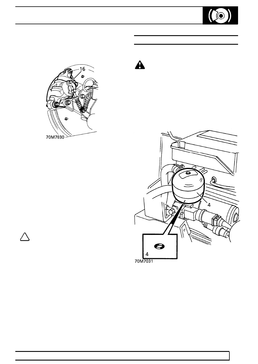
16. Bleed each rear caliper, driver’s side caliper first,

as follows: Open bleed screw, depress brake
pedal slowly and progressively.

17. Switch on ignition for 4 seconds. Switch off

ignition for 4 seconds. Repeat until fluid is clear
of air bubbles.

18. Switch off ignition, close bleed screw, release

pedal.

19. Switch on ignition, wait for ABS pump to stop

running. Press brake pedal down firmly and fully
release it five times.

20. With ignition on, repeat front caliper bleed

instructions 9. to 12. Use only the lower two
thirds of pedal travel when bleeding.

21. Repeat instruction 19.
22. Check/top up reservoir fluid level,

See this

section.

NOTE: If ABS pump makes a ticking noise
when running during this procedure,
repeat instructions 13. to 19. When the

bleed procedure has been successfully
completed, the ABS pump will not make any
ticking noises.

ACCUMULATOR

Service repair no - 70.65.21

WARNING: The accumulator is precharged
with nitrogen at a pressure of up to 80 bar
(1160 lbf/in

2

). Handle with extreme caution.

DO NOT puncture or burn if disposal is necessary.

Remove

1. Disconnect battery negative lead.
2. Depressurise system.

See this section.

3. Position cloth beneath accumulator to catch any

fluid spillage.

4. Remove accumulator. Discard ’O’ ring.

70

BRAKES

NEW RANGE ROVER

4

REPAIR

Disposal

WARNING: It is essential that safety
goggles are worn when carrying out this
procedure.

5. Secure accumulator firmly in a suitable vice.
6. Drill 5 mm hole in top of accumulator to

depressurise nitrogen chamber.

7. Dispose of accumulator in an approved manner

Refit

8. Using a new ’O’ ring, fit accumulator to pump.
9. Reconnect battery negative lead.

10. Bleed braking system.

See this section.

ACCUMULATOR PRECHARGE - CHECK

The diaphragm type accumulator is precharged with
nitrogen at 80 bar (1160 lbf/in

2

), its function is to store

hydraulic energy. Over a period of years, a normal
loss of precharge will occur. This procedure will
indicate the extent to which precharge pressure has
fallen.

NOTE: A new accumulator at 20

°

C has a

nominal pressure of 80 bar (1160 lbf/in

2

).

Minimum acceptable pressure is 50 bar

(725 lbf/in

2

).

1. Depressurise braking system.

See this section.

2. Remove 3 nuts securing pump/motor assembly

to valance. Raise assembly from mounting to
allow clearance for pressure test adaptor.

3. Remove banjo bolt securing high pressure hose

to pump. Collect sealing washers.

ABS

5

REPAIR

4. Connect pressure gauge to pump using

LRT-70-003 through high pressure hose union.

NOTE: Use original sealing washers.

5. Switch ignition on. Observe pressure gauge.
6. Pressure will rapidly rise to the accumulator

precharge value, point X, at which point rate of
increase will reduce as pressure rises to system
pressure of approx. 170 bar - see graph ’A’.

7. With a new accumulator, point ’X’ will occur at 80

bar.

8. Renew accumulator if point ’X’ occurs below 50

bar.

9. Depressurise system. Remove test equipment.

10. Using new sealing washers, position high

pressure hose to pump. Secure with banjo bolt.
Tighten to

24 Nm. (18 lbf.ft)

11. Align pump/motor assembly to mounting. Secure

with nuts. Tighten to

8 Nm. (6 lbf.ft)

12. Bleed brake system.

See this section.

HYDRAULIC BOOSTER UNIT

Service repair no - 70.65.20

Remove

1. Disconnect battery negative lead.
2. Depressurise braking system.

See this section.

3. RHD Vehicles Only: Release coolant expansion

tank from clips and bracket. Position tank aside
for access to booster pipe connections.

4. LHD Diesel Vehicles Only: Remove 2 bolts

securing fuel filter assembly to chassis turret.
Move filter aside.

5. Position cloth under booster to collect fluid

spillage.

6. Release clip from fluid reservoir hose at pump.

Disconnect hose.

7. Allow fluid to drain into suitable container.

Discard fluid. Plug hose and pump.

8. Disconnect hose from reservoir. Plug hose and

reservoir.

70

BRAKES

NEW RANGE ROVER

6

REPAIR

Manual Vehicles only.

9. Reposition container beneath clutch master

cylinder feed hose.

10. Disconnect clutch hose from reservoir. Allow

fluid to drain. Plug hose and reservoir.

All Models.

11. Disconnect 2 multiplugs from booster.
12. Disconnect fluid level switch multiplug.
13. Remove banjo bolt securing high pressure hose

to pump. Discard sealing washers. Plug hose
and pump.

14. Unscrew pipe unions from booster. Plug pipes

and booster.

15. Remove closing panel.

See CHASSIS AND

BODY, Repair. Remove stop light switch. See
this section.

16. Release booster push rod from brake pedal.

17. Remove 2 bolts securing booster assembly to

pedal box. Remove booster.

18. Remove banjo bolt securing high pressure hose

to booster. Discard sealing washers. Plug hose
and booster.


Content   ..  202  203  204  205   ..