Range Rover. Manual - part 191
ELECTRONIC AIR SUSPENSION
25
REPAIR
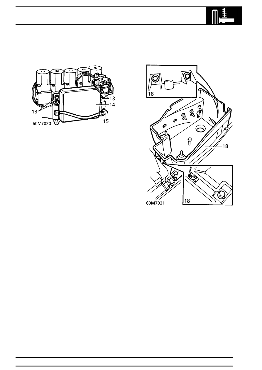
Drive Pack
13. Remove 4 screws securing drive pack to valve
block.
14. Disconnect 2 drive pack multiplugs, remove
drive pack.
Valve Block
15. Remove compressor hose from valve block.
16. Seal exposed hose and valve block.
17. Remove rear support bracket from multiplug.
Air Supply Unit
18. Remove 4 bolts securing air supply unit, remove
unit.
Refit
19. Fit air supply unit, fit and tighten bolts.
20. Remove seals from compressor hose and valve
block. Clean end of hose, fit hose to valve block
and tighten union nut.
21. Position drive pack to valve block, connect
multiplugs.
22. Align drive pack to valve block. Fit support
brackets, fit and tighten Allen screws.
23. Remove seals from pressure switch and valve
block.
24. Clean pressure switch, apply LOCTITE 572 to
thread of switch. Fit switch to valve block.
Tighten to
23 Nm. (17 lbf.ft)
25. Connect pressure switch leads to multiplug.
26. Fit valve block and drive pack assembly to air
supply unit. Secure with bolts.