Range Rover. Manual - part 189


  Index      Land Rover     Range Rover P38 - service manual 1995 year


Search            


Content   ..  187  188  189  190   ..


Range Rover. Manual - part 189


ELECTRONIC AIR SUSPENSION

17

REPAIR

Refit

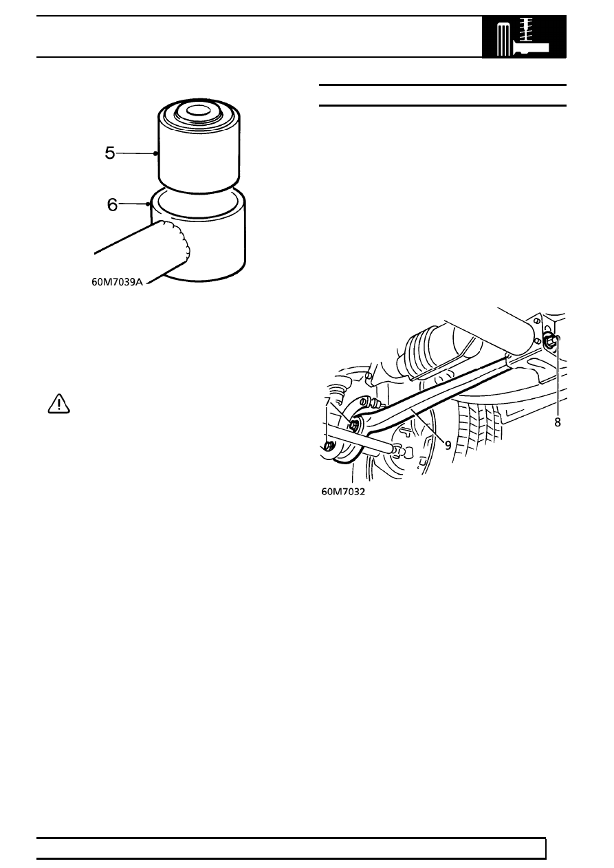
6. Clean bush mating faces in rod.
7. Fit replacement bushes centrally in rod.

CAUTION: When pressing in the new
bushes ensure that pressure is applied to
ONLY the outer edge of the bush, NOT to

the rubber inner.

8. Fit panhard rod to axle and chassis.
9. Fit securing nut and bolt. Tighten to

200Nm.

(148 lbf.ft)

10. Fit securing bolt. Tighten to

200 Nm. (148 lbf.ft)

11. Fit locking plate and secure with screw. Tighten

screw Tighten to

20Nm (15 lbf.ft)

12. Remove safety stands. Lower vehicle.

RADIUS ARM AND BUSHES

Service repair no - 60.10.16

Remove

1. Depressurise air suspension.

See this section.

2. Remove anti-roll bar.

See this section.

3. Remove front road wheel.
4. Remove nut, disconnect track rod from swivel

hub. Move rod aside.

5. Remove nut, disconnect height sensor link from

radius arm.

6. Support axle on a jack.
7. Remove nuts and bolts securing radius arm to

axle.

8. Remove nut securing radius arm to chassis

bracket.

9. Remove radius arm.

10. Press bushes from radius arm using

LRT-60-004.

60

FRONT SUSPENSION

NEW RANGE ROVER

18

REPAIR

Refit

11. Clean radius arm, lubricate bushes and their

mating faces.

12. Fit rubber bushes using LRT-60-004.

13. Fit radius arm and tighten chassis fixings to

160 Nm. (118 lbf.ft)

14. Tighten fixings to axle to

125 Nm. (92 lbf.ft)

15. Fit anti-roll bar, connect height sensor link and

track rod.

16. Remove safety stands. Lower vehicle.
17. Repressurise air suspension.

SHOCK ABSORBER

Service repair no - 60.30.02

Remove

WARNING: Unrestricted movement of a
pressurised air spring will result in failure
of the assembly, causing component

damage and possible personal injury. It is
possible to remove the shock absorber without
depressurising air springs, BUT the distance
between the axle and chassis must be held as if
the shock absorber was still fitted. This is
achieved by supporting the vehicle on safety
stands, with a jack under the axle.

1. Raise the vehicle.

WARNING: Support on safety stands.

2. Support axle on jack.
3. Remove front road wheel.

WARNING: Do not lower axle when shock
absorber is removed. This may result in air
spring damage.

4. Remove lower shock absorber retaining nut.

ELECTRONIC AIR SUSPENSION

19

REPAIR

5. Remove upper shock absorber retaining bolt.

6. Remove shock absorber.

Refit

7. Fit shock absorber.
8. Fit upper and lower fixings. Ensure lower

mounting rubbers are fitted as shown.

9. Tighten upper retaining bolt to

125 Nm.

(92 lbf.ft)

10. Tighten lower retaining nut to

45 Nm. (33 lbf.ft)

11. Refit front road wheel, tighten nuts to

108 Nm.

(80 lbf.ft) .

12. Remove jack.
13. Remove safety stands. Lower vehicle.

SWIVEL HUB

Service repair no - 60.15.19

Remove

1. Remove front hub and drive shaft assembly.

See this section.

2. Remove 2 nuts securing track rod and drag link

to swivel hub.

3. Break taper joints, move track rod and drag link

aside.

4. Remove 2 nuts securing joints to swivel hub.
5. Break taper joints using LRT-54-009 and remove

swivel hub. If joint pin turns in taper, use a 6mm
Allen key to restrain.

60

FRONT SUSPENSION

NEW RANGE ROVER

20

REPAIR

6. Remove taper collet from swivel hub.

Refit

7. Clean taper registers in swivel hub and collet.
8. Fit taper collet into swivel, until a 4 mm (0.16 in)

gap exists between the shoulder of the collet and
the swivel.

9. Fit swivel hub to axle. Fit upper joint nut. Holding

joint with Allen key, tighten nut to

110 Nm.

(81 lbf.ft).

10. Clean seal register in axle case.
11. Turn clamp screw of LRT-54-006/1 fully

anti-clockwise. Ensure that clamp toggle rotates
freely. Locate tool into axle casing with ’TOP’
mark upwards.

12. Ensure tool is located correctly in seal register,

tighten clamp screw. Using a copper mallet, tap
end of clamp screw to ensure correct seating.
Tighten clamp screw if necessary.

13. Fit and tighten lower swivel joint nut until the

taper is seated in the collet, but the collet can
still turn. Adjust the height of the hub using taper
collet until LRT-54-006/2 is a sliding fit in hub.

14. Remove LRT-54-006/2. Tighten collet 1.25 turns

to allow for further seating into taper when
tightening lower swivel joint nut.

15. Tighten lower swivel joint nut. Tighten to

135 Nm. (100 lbf.ft).

16. Check adjustment of swivel hub using

LRT-54-006/2.

17. If swivel hub is out of adjustment, loosen lower

swivel joint nut, break taper. Reseat taper into
collet, turn collet as required. If swivel hub is
high, tighten collet, if it is low, loosen collet.
Retorque lower swivel nut. Recheck adjustment
using tool LRT-54-006/2.

18. Loosen clamp screw, remove LRT-54-006/1

from axle casing.

19. Clean drag link and track rod end mating faces,

connect to swivel hub.

20. Tighten track rod and drag link nuts to

50 Nm

(37 lbf.ft)

21. Fit front hub and drive shaft assembly.

See this

section.


Content   ..  187  188  189  190   ..