Range Rover. Manual - part 190


  Index      Land Rover     Range Rover P38 - service manual 1995 year


Search            


Content   ..  188  189  190  191   ..


Range Rover. Manual - part 190


ELECTRONIC AIR SUSPENSION

21

REPAIR

SWIVEL HUB - CHECK/ADJUST

Service repair no - 60.15.13

NOTE: This procedure must be followed to
ensure the axle assembly is in correct
alignment with the swivel hub. Incorrect

adjustment may result in oil seal failure. The
check is carried out with drive shaft assembly and
oil seal removed.

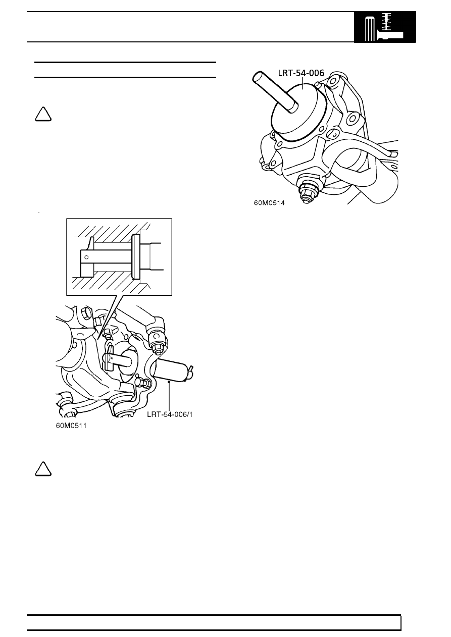
1. Clean seal register in axle case.
2. Turn clamp screw of LRT-54-006/1 fully

anti-clockwise. Locate tool into axle casing with
’TOP’ mark upwards.

NOTE: Ensure that clamp toggle rotates
freely.

3. Ensure tool is correctly located in seal register,

tighten clamp. Using a copper mallet, tap end of
clamp screw to ensure correct seating. Tighten
clamp screw if necessary.

4. Insert LRT-54-006/2 to check height of hub.

Adjustment is correct if the tool is a sliding fit in
hub.

5. If adjustment is required, note whether swivel

hub requires raising or lowering.

6. Remove LRT-54-006/2. Loosen lower swivel

joint nut, break taper.

7. Reseat taper into collet, tighten lower swivel joint

nut until the taper is seated in the collet, but the
collet can still turn.

8. Turn collet as required. If swivel hub is high,

tighten collet, if it is low, loosen collet. Note that
the thread on the collet is very fine.

9. Tighten lower swivel joint nut. Tighten to

135 Nm. (100 lbf.ft).

10. Recheck adjustment using tool LRT-54-006/2.

Repeat procedure if necessary.

11. Loosen clamp screw, remove LRT-54-006/1

from axle casing.

12. Fit hub and drive shaft assembly.

See this

section.

60

FRONT SUSPENSION

NEW RANGE ROVER

22

REPAIR

BALL JOINT - UPPER

Service repair no - 60.15.02

CAUTION: Each ball joint can be replaced
up to three times before the axle yoke bore
becomes oversize. before commencing

work, clean surrounding area of joint to be
renewed and check for yellow paint marks. If any
more than 2 marks are found, axle case must be
renewed.

Remove

1. Remove swivel hub.

See this section.

2. Fit adaptor LRT-54-008/4 to base tool and

secure with screw.

3. Fit base tool to upper joint.
4. Fit adaptor LRT-54-008/5.
5. Press upper joint from axle.

NOTE: When ram leadscrew reaches end
of stroke, retract leadscrew, screw ram
into base tool and repeat operation until

joint is free from axle yoke.

6. Remove screw and collect adaptor from base

tool.

Refit

7. Clean joint location and surrounding area of axle

yoke.

8. Make a 12mm wide yellow paint stripe on axle

yoke, adjacent to joint location.

9. Fit adaptor LRT-54-008/8 to base tool and

secure with screw.

10. Position joint to axle yoke.
11. Fit LRT-54-008/7 to base tool and position base

tool assembly over joint and axle.

12. Align tool assembly and press joint into axle.

NOTE: Align tool assembly between each
stroke of the ram until the joint is fully
seated.

CAUTION: Damage to joint boot will result
if tool is not correctly aligned during
fitment.

13. Remove base tool assembly.
14. Fit swivel hub.

See this section.

ELECTRONIC AIR SUSPENSION

23

REPAIR

BALL JOINT - LOWER

Service repair no - 60.15.03

CAUTION: Each ball joint can be replaced
up to three times before the axle yoke bore
becomes oversize. before commencing

work, clean surrounding area of joint to be
renewed and check for yellow paint marks. If more
than 2 marks are found, axle case must be
renewed.

Remove

1. Remove swivel hub,

See this section.

2. Fit adaptor LRT-54-008/10 to base tool and

secure with screw.

3. Fit adaptor LRT-54-008/11 to underside of lower

joint.

4. With assistance, fit base tool assembly onto

joint.

5. Press lower joint from axle.

NOTE: When ram leadscrew reaches end
of stroke, retract leadscrew, screw ram
into base tool and repeat operation until

joint is free from axle yoke.

6. Remove screw and collect adaptor from base

tool.

Refit

7. Clean joint location and surrounding area of axle

yoke.

8. Make a 12mm wide yellow paint stripe on axle

yoke, adjacent to joint location.

9. Fit adaptor LRT-54-008/13 to base tool and

secure with screw.

10. Position base tool assembly to axle yoke.
11. Fit lower joint to adaptor LRT-54-008/14

12. Fit adaptor and joint assembly onto base tool.
13. Align tool assembly and press joint into axle.

NOTE: Align tool assembly between each
stroke of the ram until the joint is fully
seated.

CAUTION: Damage to joint boot will result
if tool is not correctly aligned during
fitment.

14. Remove base tool assembly.
15. Fit swivel hub.

See this section.

60

FRONT SUSPENSION

NEW RANGE ROVER

24

REPAIR

SOLENOID VALVE BLOCK AND DRIVE PACK

Service repair no - 60.50.07 - Pressure switch
Service repair no - 60.50.42 - Solenoid valve drive
pack
Service repair no - 60.50.11 - Valve block
Service repair no - 60.50.44 - Air supply unit

WARNING: The system is pressurised up
to 10 bar. Dirt or grease must not enter the
system. Wear hand, ear and eye safety

standard protection when servicing system.

Remove

Petrol Vehicles Only:

1. Disconnect vacuum dump hose from ’T’ piece on

cruise control actuator.

2. Remove 2 screws securing actuator bracket to

air supply unit. Move actuator aside.

All Models:

3. Depressurise system.

See this section.

4. Remove air compressor.

See this section.

5. Disconnect all air pipes. Remove exhaust

silencer from valve block.

6. Seal exposed air hoses and valve block.
7. Release harness from 2 clips inside air supply

unit. Disconnect multiplug from valve block,
move harness aside.

8. Release valve block multiplug and clips from

unit.

9. Remove 3 screws, remove valve block from unit.

Pressure Switch

10. Disconnect pressure switch multiplug.

11. Remove pressure switch.
12. Seal switch and valve block.


Content   ..  188  189  190  191   ..