Range Rover. Manual - part 116


  Index      Land Rover     Range Rover P38 - service manual 1995 year


Search            


Content   ..  114  115  116  117   ..


Range Rover. Manual - part 116


BMW DIESEL

1

DESCRIPTION AND OPERATION

DIESEL COOLING SYSTEM

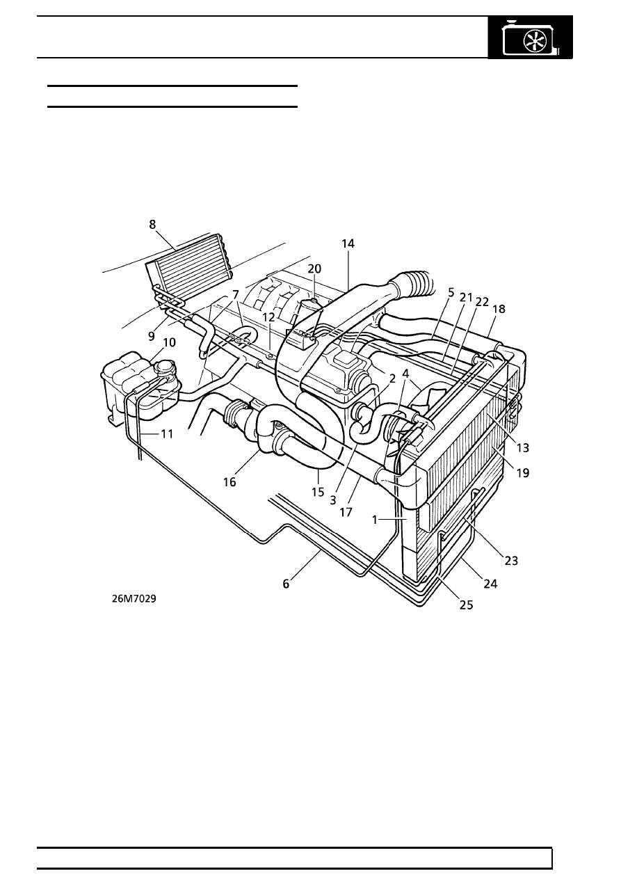
The complete cooling system installed in vehicles with
diesel engines incorporates four independent cooling
functions:- Engine (coolant) cooling; Turbo (charge
air) intercooling; Engine oil cooling; Gearbox oil
cooling.

Both intercooler and engine oil cooler are mounted in
front of the radiator while the gearbox oil cooler on
manual vehicles is an integral part of the radiator.
Pre-formed pipes/hoses are used to link the
components within the separate systems, as shown in
26M7029.

Engine cooling system

1. Radiator
2. Thermostat housing
3. Radiator return hose
4. Viscous fan and water pump
5. Radiator top hose
6. Radiator bleed pipe
7. Heater feed pipe
8. Heater matrix
9. Heater return pipe

10. Expansion tank
11. Overflow/breather pipe
12. Crankcase
13. Intercooler
14. Cross-over duct
15. Link hose
16. Turbocharger
17. Inlet pipe
18. Feed hose

19. Engine oil cooler
20. Oil filter
21. Feed pipe, engine oil cooler
22. Return pipe, engine oil cooler
23. Gearbox oil cooler (manual

gearbox, oil cooler shown)

24. Feed pipe, gearbox oil cooler
25. Return pipe, gearbox oil

cooler

26

COOLING SYSTEM

NEW RANGE ROVER

2

DESCRIPTION AND OPERATION

ENGINE COOLING

Description

The 2.5 litre diesel engine uses a pressurized cooling
system and a vertical flow, two row matrix radiator. An
expansion tank, mounted on the RH side of the
engine compartment, provides a fluid reservoir for the
coolant system.

A belt driven centrifugal water pump, complete with
viscous fan, is fitted to the engine front timing cover
and pumps coolant to the engine crankcase and
cylinder head. The thermostat housing, located at the
front of the crankcase, see 26M7030, is fitted with a
separate vent valve.

Engine cooling system

1. Radiator
2. Thermostat/housing
3. Radiator return hose
4. Viscous fan and water pump
5. Radiator top hose
6. Radiator bleed pipe

7. Heater feed pipe
8. Heater matrix
9. Heater return pipe

10. Expansion tank
11. Overflow/breather pipe
12. Crankcase

BMW DIESEL

3

DESCRIPTION AND OPERATION

COOLANT CIRCULATION

Operation

When the engine is started from cold, the thermostat,
integral in the housing (2), prevents any coolant
circulation through the radiator by closing off the
supply from the radiator. During the engine warm up,
the water pump (4) pumps coolant around the
cylinders in the crankcase (12) and through separate
galleries to the cylinder head. At the rear LH side of
the cylinder head, a proportion of the flow is diverted
through a heater feed pipe (7). The heater feed pipe is
connected to the heater matrix (8), which is housed in
the distribution unit of the heating and ventilation
system. This coolant is then carried, via the heater
return pipe (9) back to the water pump. The remaining
coolant flows through a bypass port at the front of the
cylinder head back to the water pump to complete the
cycle.

When normal engine running temperature is reached,
the thermostat opens and a secondary valve closes
the bypass port. With the thermostat open, coolant is
circulated through the top hose (5) to the radiator.
Coolant is drawn from the base of the radiator by the
water pump. Coolant circulation through the
crankcase and cylinder head to the heater matrix
remains the same.

An integral bleed pipe (6), connects the top of the
radiator to the expansion tank and aids bleeding of air
from the coolant system. The expansion tank cap
contains a pressure valve which allows excessive
pressure and coolant to vent to the overflow pipe (11)
if the system has been overfilled.

VISCOUS FAN

The viscous drive unit for the cooling fan on diesel
engines work on the same principal as that fitted on
V8 engines but is of slightly different size.

See this

section.

26

COOLING SYSTEM

NEW RANGE ROVER

4

DESCRIPTION AND OPERATION

INTERCOOLER

Description

The intercooler (1) is an aluminium heat exchanger,
with integral side tanks, comprising a single row
matrix incorporating fifteen internal cooling tubes. A
cross-over duct (2) directs air from the air cleaner,
through a link hose (3) to the turbocharger (4). Air is
directed under pressure from the turbocharger to the
intercooler via the pre-formed inlet pipe (5). The
cooled air is fed to the inlet manifold through the feed
hose (6), see 26M 7031.

Intercooler

1. Intercooler
2. Cross-over duct
3. Link hose
4. Turbocharger
5. Inlet pipe
6. Feed hose

Operation

The 2.5 litre diesel has a high power output and is
subject to high running temperatures. Compression in
the turbocharger heats the air considerably, so that it
expands. As a result the air charge mass per cylinder
is reduced, having a negative effect on power output.
The charge-air intercooler cools the air before it
reaches the cylinders, thus increasing its density. This
increases power output through increased mass of
oxygen in the combustion process as well as
maximising engine durability through maintaining
lower piston and head temperatures.


Content   ..  114  115  116  117   ..