Range Rover. Manual - part 108


  Index      Land Rover     Range Rover P38 - service manual 1995 year


Search            


Content   ..  106  107  108  109   ..


Range Rover. Manual - part 108


LAND ROVER V8

33

REPAIR

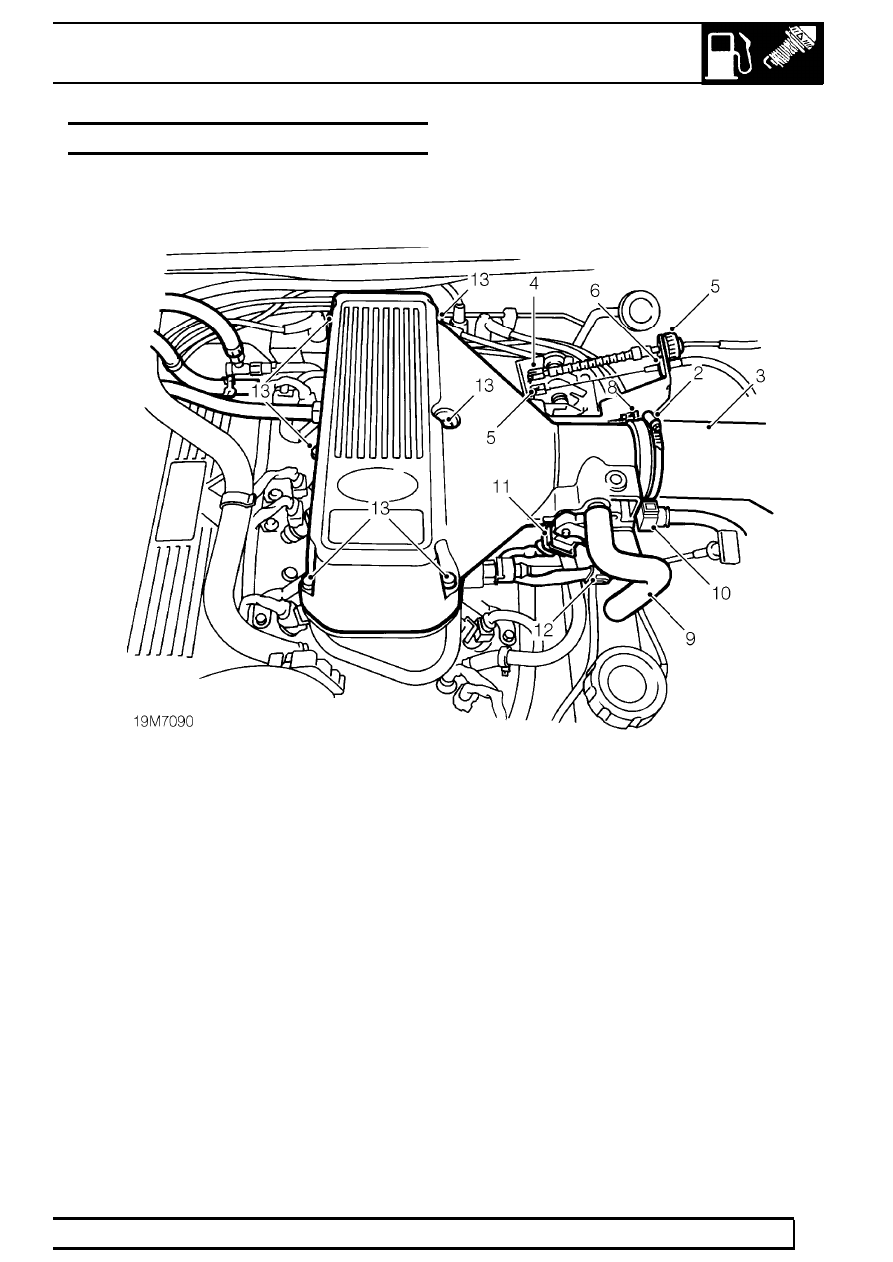
PLENUM CHAMBER - 97MY to 99MY

Service repair no - 19.22.46

Remove

1. Remove battery cover and disconnect battery.
2. Loosen clip securing air intake hose to plenum

chamber.

3. Disconnect air intake hose from plenum

chamber.

4. Remove split pin and clevis pin securing throttle

cable to throttle linkage.

5. Remove split pin and clevis pin securing cruise

control cable to throttle linkage and release
cable adjuster from abutment bracket.

6. Remove ’C’ clip securing cruise control cable

abutment to bracket and position cable aside.

7. Release clip securing throttle cable abutment to

bracket and position cable aside.

8. Release clip securing harness to cable abutment

bracket and position aside.

9. Disconnect breather hose from plenum chamber.

10. Release clip and disconnect purge hose from

plenum chamber.

11. Disconnect multiplug from throttle potentiometer.
12. Disconnect multiplug from stepper motor.
13. Remove 6 bolts securing plenum chamber to

ram housing.

14. Release plenum chamber from ram housing.
15. Fit hose clamp to 2 plenum chamber coolant

hoses.

16. Position cloth to catch spillage.

19

FUEL SYSTEM

NEW RANGE ROVER

34

REPAIR

17. Release clip securing coolant hose to plenum

water jacket and disconnect hose.

18. Loosen clip securing coolant hose to plenum

water jacket and disconnect hose.

19. Remove plenum chamber assembly.
20. Place clean cloth over intake pipes to prevent

dirt ingress.

Do not carry out further dismantling if
component is removed for access only.

21. Remove 4 bolts securing water jacket to plenum

chamber.

22. Remove water jacket and sealing gasket.
23. Position throttle linkage to gain access to bolt.

24. Remove 3 bolts securing throttle linkage to

plenum chamber.

25. Remove throttle linkage and bracket.
26. Collect spring.

27. Remove 2 bolts securing throttle potentiometer

to plenum chamber.

28. Collect clamp plate.
29. Remove throttle potentiometer.
30. Remove 2 bolts securing stepper motor to

plenum chamber.

31. Remove stepper motor and collect gasket.
32. Position throttle linkage bracket and spring to

plenum chamber.

33. Engage spring to linkage.
34. Fit bolts securing throttle linkage to plenum and

tighten to

8 Nm (6 lbf.ft)

35. Clean mating faces of throttle potentiometer and

stepper motor.

36. Fit throttle potentiometer, ensuring spindle is

correctly engaged.

37. Fit retaining plate and bolts and tighten to

2 N.

(1.5 lbf.ft)

38. Fit NEW stepper motor gasket to plenum

chamber.

39. Fit stepper motor.
40. Fit bolts securing stepper motor to plenum

chamber and tighten to

2 Nm (1.5 lbf.ft)

41. Clean mating faces of water jacket and plenum

chamber.

42. Fit NEW water jacket gasket to plenum chamber.
43. Fit water jacket to plenum chamber.
44. Fit bolts securing water jacket to plenum

chamber and tighten to

13 Nm (10 lbf.ft)

LAND ROVER V8

35

REPAIR

Refit

45. Clean mating faces of plenum chamber and ram

housing.

46. Connect coolant hose to water jacket and secure

with clip.

47. Connect second coolant hose to water jacket

and secure with clip.

48. Remove hose clamps.
49. Apply a thin, uniform coating of Loctite 577

sealant to mating face of plenum chamber.

50. Fit plenum chamber to ram housing.
51. Fit bolts securing plenum chamber to ram

housing and tighten to

24 Nm (18 lbf.ft)

52. Connect multiplugs to stepper motor and throttle

potentiometer.

53. Connect purge hose to plenum chamber. Ensure

connector is securely mated.

54. Connect breather hose to plenum chamber.
55. Position harness to throttle linkage bracket and

secure clip.

56. Engage throttle cable abutment clip to bracket.
57. Align throttle cable to throttle linkage, fit clevis

pin and split pin.

58. Position cruise control cable abutment to bracket

and secure with ’C’ clip.

59. Align cruise control cable to throttle linkage, fit

clevis pin and split pin.

60. Adjust throttle cable.

See Adjustment.

61. Connect air intake hose to plenum chamber and

secure with clip.

62. Connect battery and fit cover.
63. Top up cooling system.
64. Check base idle speed. Adjust if necessary.

If 4.6

See ENGINE TUNING DATA, Information.

If 4.0

See ENGINE TUNING DATA, Information.

PLENUM CHAMBER - from 99MY

Service repair no - 19.22.46

Remove

1. Remove upper inlet manifold gasket.

See

MANIFOLD AND EXHAUST SYSTEM, Repair.

2. Remove 4 bolts securing throttle body to plenum

chamber, remove throttle body and collect
gasket.

3. Remove breather hose adaptor.
4. Remove 4 bolts securing plenum chamber to

upper manifold and remove plenum chamber.

5. Collect plenum chamber gaskets.

Refit

6. Clean plenum chamber and upper manifold

mating faces.

7. Using new gaskets, position plenum chamber, fit

bolts and tighten to

22 Nm (16 lbf.ft).

8. Fit and tighten breather adaptor to

6 Nm (4.5

lbf.ft).

9. Clean plenum chamber and throttle body mating

faces.

10. Using a new gasket, position throttle body, fit

bolts and tighten to

9 Nm (6 lbf.ft).

11. Fit upper inlet manifold gasket.

See MANIFOLD

AND EXHAUST SYSTEM, Repair.

19

FUEL SYSTEM

NEW RANGE ROVER

36

REPAIR

FUEL FILTER

Service repair no - 19.25.02

Remove

1. Disconnect battery negative lead.
2. Depressurise fuel system.

See this section.

3. Raise the vehicle.

WARNING: Support on safety stands.

4. Position container beneath fuel filter to catch

spillage.

5. Disconnect fuel hoses from filter.

6. Remove ’O’ rings and discard.
7. Remove bolt securing filter and strap assembly.

Remove assembly.

Refit

8. Transfer strap to new fuel filter.
9. Position filter and strap assembly to floor pan.

Ensure that flow arrow points toward front of
vehicle.

10. Secure filter strap with bolt.
11. Using new ’O’ rings, connect fuel hoses to filter.

Tighten to

20 Nm (15 lbf.ft)

12. Remove container beneath filter.
13. Remove safety stands. Lower vehicle.
14. Reconnect battery negative lead.


Content   ..  106  107  108  109   ..