Range Rover. Manual - part 53


  Index      Land Rover     Range Rover P38 - service manual 1995 year


Search            


Content   ..  51  52  53  54   ..


Range Rover. Manual - part 53


LAND ROVER V8

31

REPAIR

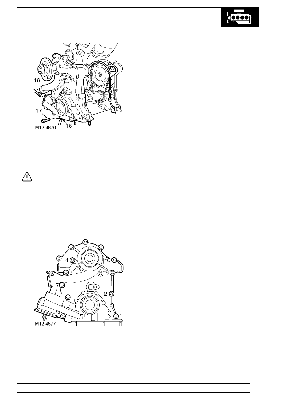
16. Loosen unions and disconnect oil cooler feed

and return pipes from front cover , remove and
discard ’O’ rings.

CAUTION: Plug the connections.

17. Remove 9 bolts securing front gear cover and

remove cover. Remove and discard gasket.

Refit

18. Clean mating faces of front cover and cylinder

block. Clean dowels and dowel holes.

19. Fit new gasket onto dowels in cylinder block.

20. Fit front cover to cylinder block and tighten bolts

in sequence shown to

22 Nm (16 lbf.ft). Ensure

CMP sensor multiplug bracket is secured by bolt.

21. Fit new ’O’ rings to oil cooler pipes, connect

pipes to front cover and tighten unions to

15 Nm

(11 lbf.ft).

22. Fit bolt securing oil cooler return pipe to

alternator mounting bracket.

23. Connect Lucar to oil pressure switch.
24. Connect multiplug to CMP sensor.
25. Ensure oil filter seal and mating face on front

cover is clean.

26. Lubricate seal with clean engine oil and fit

engine oil filter.

27. Fit radiator cowl and secure with clips.
28. Fit oil cooler pipes into recesses in radiator cowl

and tighten pipe unions to

30 Nm (22 lbf.ft).

29. Fit thermostat housing to radiator cowl.
30. Connect bottom coolant hose to radiator and

secure with clip.

31. Connect hose to water pump and secure with

clip.

32. Connect top hose to radiator and secure with

clip.

33. Ensure mating faces of water pump pulley and

drive flange are clean, fit pulley and tighten bolts
to

22 Nm (16 lbf.ft).

34. Fit auxiliary belt jockey pulley and tighten bolt to

50 Nm (37 lbf.ft).

35. Fit front cover oil seal.

See this section.

36. Fit oil pick-up strainer.

See this section.

37. Refill cooling system.

See COOLING SYSTEM,

Repair.

12

ENGINE

NEW RANGE ROVER

32

REPAIR

FRONT COVER AND OIL PUMP ASSEMBLY

Service repair no - 12.60.26

Remove

1. Remove front cover gasket

See this section.

2. Remove bolt securing CMP sensor, remove

clamp and sensor. Discard ’O’ ring.

3. Remove 6 bolts securing water pump, remove

pump and discard gasket.

4. Remove oil pressure switch and discard ’O’ ring.
5. Remove oil filter cartridge.

See this section.

Refit

6. Ensure oil filter cartridge adaptor thread is clean

and apply Loctite 577 sealant to thread.

7. Ensure oil pressure switch and mating face is

clean.

8. Fit new ’O’ ring and tighten switch to

15 Nm (11

lbf.ft).

9. Clean water pump and mating face.

10. Use a new gasket and fit water pump. Tighten

bolts securing water pump to

22 Nm (16 lbf.ft).

11. Ensure CMP sensor is clean, fit new ’O’ ring and

fit sensor to cover.

12. Fit clamp to CMP sensor and tighten bolt to

8

Nm (6 lbf.ft).

13. Fit front cover gasket.

See this section.

LAND ROVER V8

33

REPAIR

ENGINE MOUNTINGS - up to 99MY

Service repair no - 12.45.01 - LH
Service repair no - 12.45.02 - RH

Remove

1. Disconnect battery negative lead.
2. With assistance, release bonnet struts from body

locations. Retain bonnet in vertical position using
stay clips.

WARNING: Only open the bonnet to the
vertical position with the vehicle on a
horizontal surface in the workshop. This

position is not intended to be used outdoors
where the bonnet could be affected by winds.

3. Right Hand Mounting Only: Fit lifting eye to

alternator bracket.

4. RHD - Right Hand Mounting Only: Remove

steering column intermediate shaft.

See

STEERING, Repair.

5. Left Hand Mounting Only: To prevent strain on

cruise control cable, disconnect from abutment
and actuator diaphragm.

6. Raise vehicle on four post lift.

7. Remove 4 nuts securing mounting to chassis

and engine. Discard nuts.

12

ENGINE

NEW RANGE ROVER

34

REPAIR

8. Connect hoist to lifting eye. Raise relevant side

of engine.

CAUTION: Raise engine by minimum
necessary to remove mounting. Ensure
ignition coils do not foul bulkhead.

9. Remove engine mounting.

Refit

10. Fit engine mounting. Ensure domed head of

centre bolt faces toward chassis.

11. Align mounting studs. Lower engine. Disconnect

hoist.

12. Fit new engine mounting flange nuts. Tighten to

45 Nm (33 lbf.ft)

13. Lower vehicle.
14. Left Hand Mounting Only: Connect cruise

control cable to abutment bracket and actuator
diaphragm.

15. Adjust cable free-play if necessary.

See

CRUISE CONTROL, Adjustment.

16. RHD - Right Hand Mounting Only: Fit steering

column intermediate shaft.

See STEERING,

Repair.

17. Right Hand Mounting Only: Remove lifting eye

from alternator bracket.

18. With assistance, release bonnet stay clips.

Engage bonnet struts.

CAUTION: Ensure bonnet stay clips are
returned to their original positions as
shown.

19. Reconnect battery negative lead.


Content   ..  51  52  53  54   ..