Range Rover. Manual - part 35


  Index      Land Rover     Range Rover P38 - service manual 1995 year


Search            


Content   ..  33  34  35  36   ..


Range Rover. Manual - part 35


BMW DIESEL

31

REPAIR

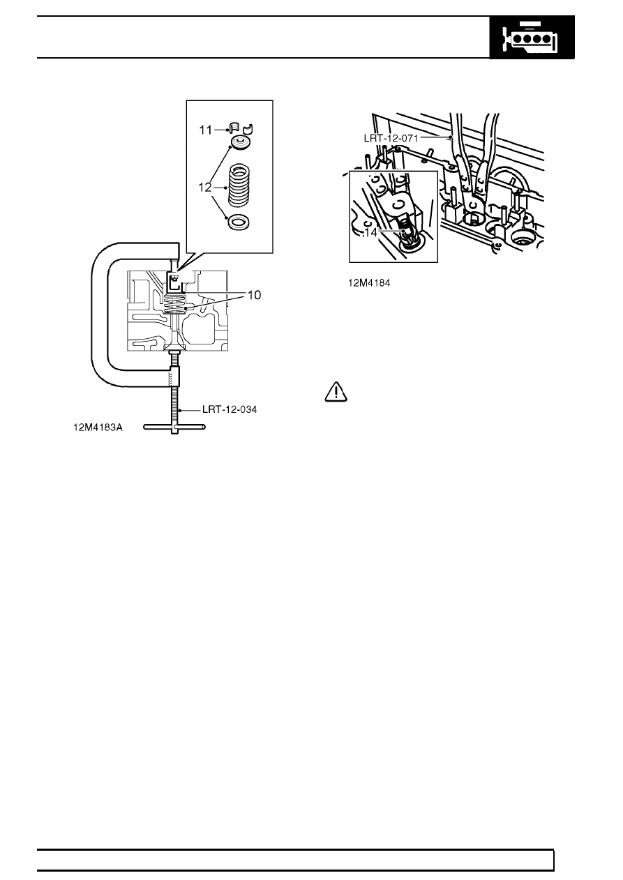
9. Position tool LRT-12-034 on valve.

10. Compress valve spring.
11. Remove 2 collets using a stick magnet.
12. Release tool LRT-12-034, collect valve spring

cup, valve spring and spring seat, discard valve
spring.

13. Remove valve stem oil seal using LRT-12-071,

discard seal.

14. Remove valve.

CAUTION: Store valve components in their
fitted order.

15. Repeat above procedures for remaining valves.
16. Clean all components.

12

ENGINE

NEW RANGE ROVER

32

REPAIR

Inspection

Valves

17. Remove carbon from valves, valve guides and

seats.

18. Check valves for signs of burning, cracking and

pitting of valve seats.

19. Check head diameter of each valve:

Inlet = 36.0 mm (1.42 in)
Exhaust = 31.0 mm (1.22 in)

20. Check stem diameter of each valve, half-way

along stem and compare diameters with
dimensions given to determine stem sizes of
valves fitted and valve stem wear.
Standard:
Inlet = 6.97 mm (0.274 in)
Service limit = 6.95 mm (0.273 in)
Exhaust = 6.95 mm (0.273 in)
Service limit = 6.93 mm (0.272 in)

1st oversize:
Inlet = 7.07 mm (0.28 in)
Service limit = 7.05 mm (0.277 in)
Exhaust = 7.06 mm (0.278 in)
Service limit = 7.04 mm (0.27 in)

2nd oversize:
Inlet = 7.17 mm (0.282 in)
Service limit = 7.15 mm (0.28 in)
Exhaust = 7.16 mm (0.281 in)
Service limit = 7.14 mm (0.279 in)

21. If valve stems are worn in excess of service

limits, valves with next oversize stems must be
fitted and valve guides reamed to correct size.

Valve guides

CAUTION: Prior to checking/reaming valve
guides, check cylinder head for warping.
See Cylinder head gasket.

22. Position a suitable DTI to cylinder head adjacent

to No.1 valve seat.

23. Insert a new valve with same stem diameter as

the original in the valve guide.

24. Position end of valve stem flush with spring end

of guide.

25. Move valve away from DTI, pre-load gauge and

note pre-load reading.

26. Move valve towards DTI, note gauge reading

and subtract pre-load from this figure. Compare
final figure obtained with tilt figure:
Valve tilt - inlet and exhaust = 0.5 mm (0.02 in).

27. If tilt figure exceeds above dimension, original

valve must be replaced with next oversize valve
and valve guide reamed to next oversize.
Valve guide inside diameter - inlet and exhaust:
Standard = 7.0 mm (0.275 in)
For 1st oversize valve stem = 7.1 mm (0.28 in)
For 2nd oversize valve stem = 7.2 mm (0.283 in)

NOTE: Valve guides may not be replaced.

BMW DIESEL

33

REPAIR

28. Dry ream valve guides using BMW tool 004210

and appropriate size reamer from those supplied
with tool.

29. Ream valve guide from combustion chamber

side, rotate tool once only in a downwards
direction; remove all traces of swarf on
completion.

Check valve head stand-down

30.

Original valves: Lap valves to their seats,
remove all traces of grinding paste on
completion.

31.

Replacement valves: Do not lap valves to their
seats.

32. Insert No.1 valve into its guide.

33. Position suitable DTI to cylinder head, pre-load

then zero gauge.

34. Position DTI to centre of valve, measure valve

head stand-down and compare with figures
given:
Inlet = 0.65 to 0.85 mm (0.02 to 0.03 in)
Exhaust = 0.85 to 1.05 mm (0.03 to 0.04 in)

35. Replace any valve having stand-down in excess

of figures given with a valve having an increased
head thickness.

36. Refer to the following to determine thickness of

valve head required ensuring that valves with
correct size stem diameter are obtained.

NOTE: It will be necessary to re-cut valve
seats when fitting valves with increased
head thickness.

Standard valve stem diameter:
Head thickness increase - 0.25 mm (0.01 in)
Identification marks - RO

12

ENGINE

NEW RANGE ROVER

34

REPAIR

1st oversize valve stem:
Head thickness increase - 0.25 mm (0.01 in)
Identification marks - R1
Head thickness increase - 0.50 mm (0.02 in)
Identification marks - R2

2nd oversize stem:
Head thickness increase - 0.50 mm (0.02 in)
Identification marks - R3

NOTE: Identification marks will be found
adjacent to cotter grooves.

Valve seat - recut

37. Recut valve seats using BMW tool 003520.

Head thickness:
0.25 mm (0.01 in) - Increase depth by 0.25 mm
(0.01 in)
0.50 mm (0.02 in) - Increase depth by 0.50 mm
(0.02 in)

38. Use BMW tool 003580 to obtain specified valve

seat dimensions:
Valve seat angle = 45

° ±

10’

Correction angle - outside = 15

°

Correction angle - inside = 60

°

Seat face outside diameter D:
Inlet valve = 35.5 mm (1.4 in)
Exhaust valve = 30.6 mm (1.2 in)
Valve seat width E:
Inlet valve = 1.75 to 2.25 mm (0.07 to 0.09 in)
Exhaust valve = 2.60 to 2.90 mm (0.10 to 0.11
in)

39. Remove all traces of swarf on completion.

CAUTION: Do not lap replacement valves
to their seats.

Refit

40. Lubricate all components including valve guides

and new valve stem oil seals with engine oil.

41. Insert protective sleeve LRT-12-101 in tappet

bore.


Content   ..  33  34  35  36   ..