Frelander 2. Manual - part 545
Item
Part Number
Description
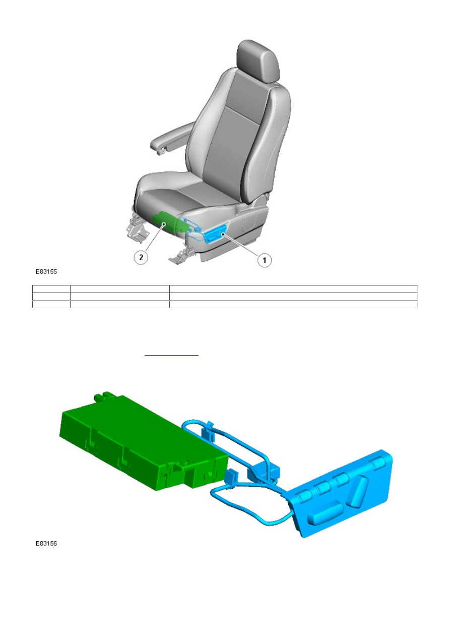
1
-
Driver's memory seat switch pack
2
-
Power seat module
The driver's power operated seat with memory is 6-way adjustable and comprises the same control components as the
front non-memory seat. The seat incorporates a power seat module located under the seat frame that allows up to 3
memory positions for the seat to be stored and recalled. If memory exterior mirrors are installed, the power seat module
also initiates movement of the exterior mirrors by transmitting a command signal to the front door control modules when
the seat memory position is recalled. The front door control modules are used to store and recall the memory exterior
mirror positions.
For additional information, refer to:
Rear View Mirrors
(501-09 Rear View Mirrors, Description and Operation).
Power Seat Module
The power seat module is connected in the wiring between the seat switch pack and seat adjustment motors. The module
contains a non-volatile Electrically Erasable Programmable Read Only Memory (EEPROM).
The power seat module monitors the seat positions and stores information provided by the seat track Hall sensors. The
Hall sensors are incorporated within the seat adjustment motors. All seat memory values and current seat motor positions
are stored in the EEPROM.
In the event of a power loss, when power is restored the current motor positions are recalled from the EEPROM memory