Frelander 2. Manual - part 541
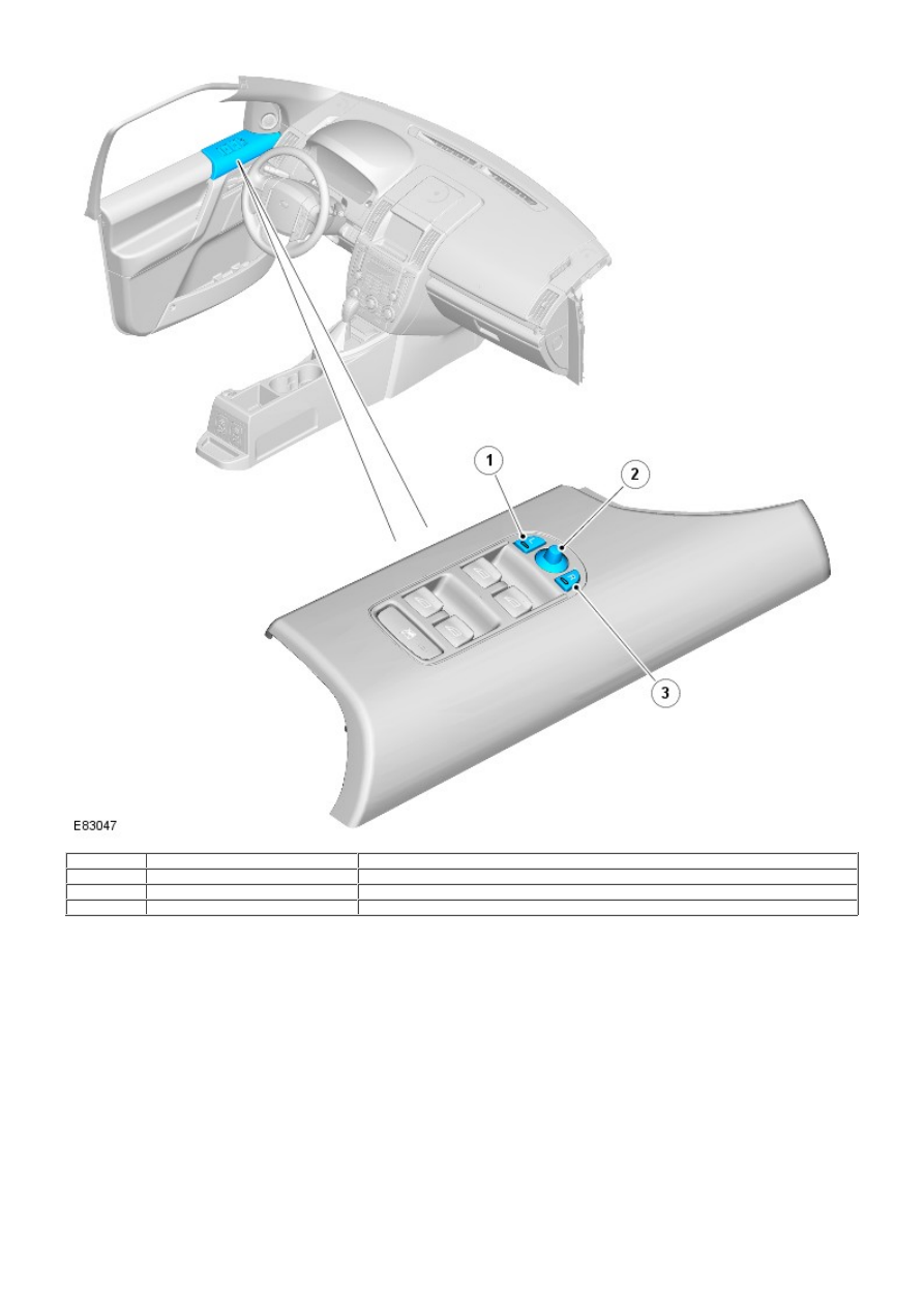
Item
Part Number
Description
1
-
LH exterior mirror select switch
2
-
4-way directional joystick
3
-
RH exterior mirror select switch
The door mirrors are controlled using a switch pack located on the driver's door. The switch pack contains 2 non-latching
mirror select switches labeled 'L' and 'R' and a 4-way directional joystick. The switch pack is connected to the driver door
control module via the LIN bus. The driver and front passenger door control modules are connected via the medium speed
CAN bus. A hardwired connection between each door control module and the corresponding door mirror, provides the supply
and ground paths for the mirror motors.
Each exterior door mirror incorporates 2 motors to control horizontal (left/right) and vertical (up/down) adjustments.
On vehicles installed with a driver's power operated memory seat and memory exterior mirrors, a potentiometer is
incorporated within each mirror motor and is used to provide information regarding the actual motor positions. The current
position and memory positions of each door mirror motor are maintained and stored within the corresponding door control
module.
The memory exterior mirror positions are also monitored and stored within door control module memory when the reverse
gear mirror dip function is used.
When reverse gear is selected, the door control modules store the current mirror positions and will then dip both the driver
and passenger mirror glass to a default dip position. While reverse gear is selected it is possible to store a preferred
dipped mirror position by adjusting the driver/passenger mirror glass to the desired position via the mirror switch pack.
When the desired position is achieved using the switches, the new dip positions will be automatically stored by the door
control modules when reverse gear is de-selected. Therefore when reverse gear is re-selected, the dip position recalled by
the door control modules will be the new reverse gear mirror dip stored position. When reverse gear is deselected the
mirror glass will automatically move to the previous stored position prior to reverse gear selection.