Frelander 2. Manual - part 505
Ironstone Way
Brixworth
Northants
NN6 9UD
United Kingdom
Telephone: +44 (0) 1327 704461
Fax: +44 (0) 1327 706632
Repair Methods
CAUTION: Several different types and sizes of terminal may be found in a single electrical connector housing.
It is necessary to identify:
The conductor (wire) size of the affected wiring harness
The electrical connector range from which the damaged wiring harness is to be removed
The terminal type
Use of the approved diagnostic tool will greatly assist in the quick identification of electrical connectors and faulty pin
terminal(s).
Reference can also be made to the vehicle Electrical Guides, held by Dealers, to identify wiring harness(s) and electrical
connector(s).
By using the Relationship Table, the wiring harness conductor (wire) size can be related to a suitable pre-terminated
wiring harness by the color of the insulation. Also, the correct length of insulation to be stripped from the wiring harness
lead is identified.
Relationship Table
CABLE RANGE
SPLICE
STRIP LENGTH
0.35 mm² to 1.50 mm²
RED
6.00 to 7.00 mm
1.00 mm² to 2.50 mm²
BLUE
6.00 to 7.00 mm
4.00 mm² to 6.00 mm²
YELLOW
9.00 to 9.50 mm
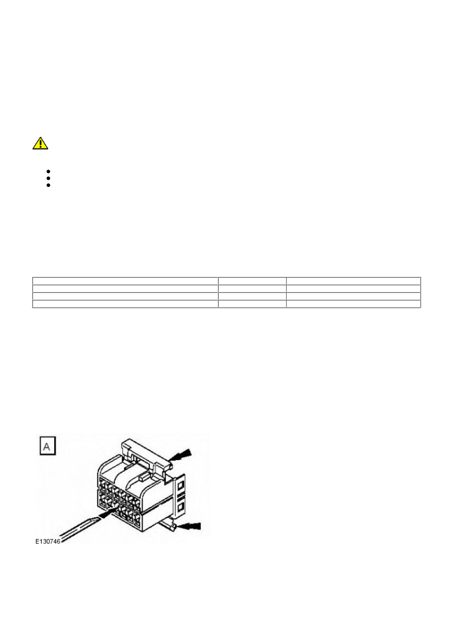
Electrical Connector Terminal Extraction
It must be noted that some electrical connector(s) have anti-backout devices which prevent the terminals from being
removed from the electrical connector. Some examples of these are shown in following illustrations. The anti-backout
device must be released before attempting to remove the terminal from the electrical connector. Some anti-backout
devices require a special tip to release the device and these have been included in the kit. Most can be released by
carefully using a suitable small screwdriver.
Various types of electrical connector have seals installed internally or externally to prevent moisture ingress. These
normally do not have to be removed but make sure that they are installed when the electrical connectors are connected.
The illustrations show examples of each tip used on different types of electrical connector(s). There are a large number of
different types of electrical connector used on vehicles therefore only one example using each tip is shown. Technicians
experience and judgement will dictate which type of tip should be used for those electrical connector(s) which are not
shown. Care should be exercised to avoid further damage when removing the terminals from the electrical connector.
• NOTE: Examples of the extraction tips and anti-backout tips.