Frelander 2. Manual - part 425


  Index      Land Rover     Land Rover Frelander 2 - service repair manual 2006-2010 year


Search            


Content   ..  423  424  425  426   ..


Frelander 2. Manual - part 425


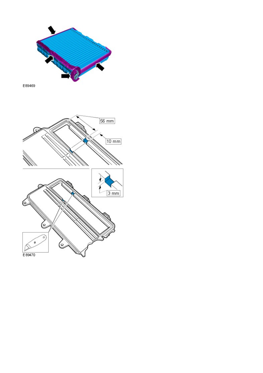
Apply the foam strips from the service kit to the
evaporator core.

1.

Install the evaporator core.

2.

Cut a slot in each side of the service door to
accommodate the heater core and evaporator core
housing.

3.


Install the service door.
Secure the 4 clips.
Install the 4 screws.

4.

Apply the asphalt tape from the service kit to the
service replacement evaporator pipes.

5.

6. 

CAUTION: Make sure that all openings are sealed. Use new

blanking caps.

Remove the TXV assembly from the service replacement evaporator
pipes.

6.

Guide the service replacement evaporator pipes through the
bulkhead so that approximately 20mm is visible in the engine
compartment.

7.

Install the TXV captive clamping plate.

8.

9. NOTE: Install new O-ring seals.

Install the service replacement evaporator pipes to the
evaporator.

Torque: 5 Nm

9.

Connect the blower motor electrical connector.

10.

11. NOTE: Install new O-ring seals.

Install the TXV assembly.

Torque: 4 Nm

11.

12. NOTE: Install new O-ring seals.

Connect the A/C pipes to the TXV and tighten the M6 nut.

Torque: 9 Nm

12.

Install the RH floor console extension.

13.

Install the brake pedal assembly.

Torque: 25 Nm

14.

Install the brake pedal clevis pin.

15.

Connect the stoplamp switch and speed control deactivator switch
electrical connectors.

16.

Secure the wiring harness to the brake pedal bracket.

17.

Install the accelerator pedal assembly.

Refer to: 

Accelerator Pedal

 (310-02 Acceleration Control, Removal

and Installation).

18.

Vehicles with automatic transmission

Install the secondary bulkhead center panel.

Refer to: 

Secondary Bulkhead Center Panel - TD4 2.2L Diesel

(501-02 Front End Body Panels, Removal and Installation).

19.

Vehicles with manual transmission

Install the clutch pedal assembly.

Refer to: 

Clutch Pedal - RHD AW D

 (308-02 Clutch Controls, Removal

and Installation).

20.

All vehicles

Install the driver lower air bag module support bracket.

Torque: 7 Nm

21.

Install the steering column.

Refer to: 

Steering Column

 (211-04 Steering Column, Removal and

Installation).

22.

Recharge the A/C system.

Refer to: 

Air Conditioning (A/C) System Recovery, Evacuation and

Charging

 (412-00 Climate Control System - General Information,

23.

General Procedures).

Connect the battery ground cable.

Refer to: 

Specifications

 (414-00 Battery and Charging System -

General Information, Specifications).

24.


Content   ..  423  424  425  426   ..