Frelander 2. Manual - part 423


  Index      Land Rover     Land Rover Frelander 2 - service repair manual 2006-2010 year


Search            


Content   ..  421  422  423  424   ..


Frelander 2. Manual - part 423


blanking caps.

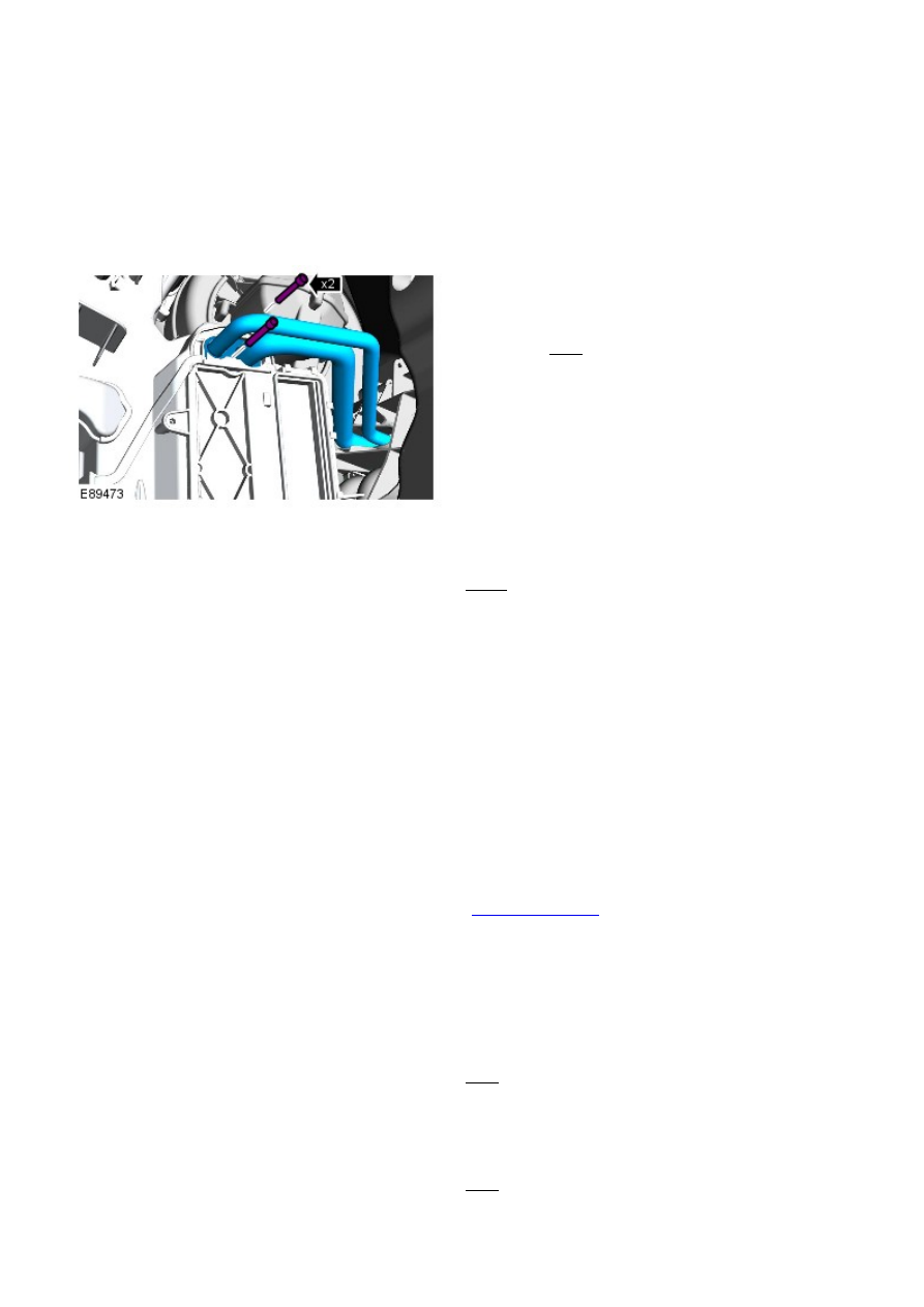
Remove the TXV assembly from the service replacement evaporator
pipes.

Guide the service replacement evaporator pipes through the
bulkhead so that approximately 20mm is visible in the engine
compartment.

7.

Install the TXV captive clamping plate.

8.

9. NOTE: Install new O-ring seals.

Install the service replacement evaporator pipes to the
evaporator.

Torque: 5 Nm

9.

Install the CJB bracket.

Torque: 10 Nm

10.

Secure the wiring harnesses to the CJB bracket.

11.

Install the CJB.

12.

Connect the 5 electrical connectors to the CJB and secure the front
carpet.

13.

Install the CJB lower access cover.

14.

Install the passenger side footwell duct.

15.

Install the glove compartment.

Refer to: 

Glove Compartment

 (501-12 Instrument Panel and

Console, Removal and Installation).

16.

Install the RH floor console extension.

17.

18. NOTE: Install new O-ring seals.

Install the TXV assembly.

Torque: 4 Nm

18.

19. NOTE: Install new O-ring seals.

Connect the A/C pipes to the TXV and tighten the M6 nut.

Torque: 9 Nm

19.

Install the anti-theft alarm horn with integral battery.

20. Install the plenum chamber panel.

21.

Refer to: 

Plenum Chamber

 (412-01 Climate Control, Removal and

Installation).

Recharge the A/C system.

Refer to: 

Air Conditioning (A/C) System Recovery, Evacuation and

Charging

 (412-00 Climate Control System - General Information,

General Procedures).

22.

Connect the battery ground cable.

Refer to: 

Specifications

 (414-00 Battery and Charging System -

General Information, Specifications).

23.

Climate Control - EvaporatorRHD AWD

Removal and Installation

Removal

• NOTE: The removal of this component involves cutting an aperture in the evaporator housing wall and cutting through
the high and low pressure A/C lines. A service repair kit is supplied to cover this procedure.

All vehicles

Make the SRS system safe.

Refer to: 

Standard W orkshop Practices

 (100-00 General Information,

Description and Operation).

1.

Recover the A/C refrigerant.

Refer to: 

Air Conditioning (A/C) System Recovery, Evacuation and

Charging

 (412-00 Climate Control System - General Information,

General Procedures).

2.

Remove the steering column.

Refer to: 

Steering Column

 (211-04 Steering Column, Removal and

Installation).

3.

Remove the driver lower air bag module support
bracket.

4.

Vehicles with manual transmission

Remove the clutch pedal assembly.

Refer to: 

Clutch Pedal - RHD AW D

 (308-02 Clutch Controls, Removal

and Installation).

5.

Vehicles with automatic transmission

Remove the secondary bulkhead center panel.

Refer to: 

Secondary Bulkhead Center Panel - TD4 2.2L Diesel

(501-02 Front End Body Panels, Removal and Installation).

6.

All vehicles

Remove the accelerator pedal assembly.

Refer to: 

Accelerator Pedal

 (310-02 Acceleration Control, Removal

and Installation).

7.

Vehicles with manual transmission

8.

Remove the brake pedal assembly.

9.

Vehicles with automatic transmission

10.


Content   ..  421  422  423  424   ..