Frelander 2. Manual - part 403


  Index      Land Rover     Land Rover Frelander 2 - service repair manual 2006-2010 year


Search            


Content   ..  401  402  403  404   ..


Frelander 2. Manual - part 403


Acceleration Control - Accelerator Pedal

Removal and Installation

Removal

• NOTE: Removal steps in this procedure may contain installation details.
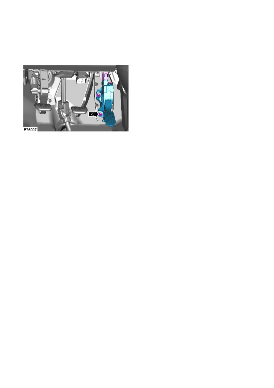
Torque: 10 Nm

1.

Installation

To install, reverse the removal procedure.

1.

Speed Control - I6 3.2L Petrol -

Torque Specifications

Description

Nm

lb-ft

Accelerator pedal assembly nuts

10

7

Speed control switch Torx bolts

3

2

Speed Control - I6 3.2L Petrol - Speed Control

Description and Operation

COMPONENT LOCATION

Item

Part Number

Description

1

-

Instrument cluster

2

-

Clockspring

3

-

Speed control steering wheel switches

4

-

Speed control inhibit switch

5

-

Stoplamp switch

6

-

Transmission Control Module (TCM)

7

-

Accelerator Pedal Position (APP)

8

-

Engine Control Module (ECM)

OVERVIEW

The speed control system maintains a set speed selected by the driver until operation is suspended or cancelled by a
further input from the driver and is controlled by the ECM.

The speed control system comprises the following components:

A set +/- switch
A RESUME switch

A CANCEL switch.

The system also uses the following:

The ECM
The stoplamp switch.
The APP sensor

The ECM controls the set speed by modifying engine speed/torque and requesting gear changes from the transmission
(automatic variants only).

The speed control system also uses inputs from the brake pedal switch, the APP sensor, the ECM and the ABS control
module.

The speed control is operated by the driver using only the steering wheel switches. When speed is active, the ECM
regulates the PW M signals to the fuel injectors to adjust the fuel supply as required to maintain the set speed.

During speed control operation, the ECM controls vehicle speed by adjusting fuel injection duration and timing. When the
accelerator pedal is pressed with speed control active, the ECM outputs a calculated throttle angle signal in place of the
actual throttle angle signals produced by the APP sensor. The calculated throttle angle is derived from fuel demand.

CONTROL SWITCHES

Item

Part Number

Description

1

-

Set target speed/increase speed

2

-

Set target speed/decrease speed

3

-

Resume set speed

4

-

Speed control suspend.

The speed control switches are located on the LH side of the steering wheel. The switches are connected via fly leads
directly to the clock spring. All the speed control switches are non-latching momentary rocker switches. The minimum set
speed is 18 mph (30 (km/h). Speed control is automatically suspended if the vehicle speed falls below 15 mph (24 km/h).

The speed control switches are resistive ladder type switches. There are three rocker switches associated with speed
control, two of which are for adaptive speed control (where specified). The switches vary the resistance of a signal voltage
sent to the ECM. The switches receive a 5 volt reference supply. The ECM measures the returned voltage to determine
which switch has been pressed.

Suspend Switch

The suspend/resume switch controls the selection of speed control. When the ignition is in position II, a single press of
the suspend switch will activate the suspend mode. This temporarily switches off the speed control system, but retains
the previously set speed in the ECM memory.

Resume Switch

A second press of the switch re-activates the previously set speed after the speed control has been suspended by pressing
the suspend switch or by depressing the brake pedal.

Set Speed/Increase/Decrease Speed (+/–) Switches

When the speed control system is active, pressing the '+' switch sets the controlled speed to the current road speed of
the vehicle. Subsequent momentary presses of the switch increases the set road speed by 0.6 mph (1 km/h). If the switch
is pressed and held the road speed will continue to increase until the switch is released. Momentarily pressing the '–'
switch, decreases the set speed by 0.6 mph (1 km/h). If the switch is pressed and held, the set speed is decreased until
the switch is released.

CONTROL DIAGRAM

• NOTE: A = Hardwired; D = High speed CAN bus


Content   ..  401  402  403  404   ..